Appliance Installation
Hardware Appliance Installation
-
Remove all packaging and rack mount the appliance if required.
-
Connect the power lead.
The power supply is an auto-sensing unit (100v to 240v). -
Connect a network cable from your switch to one of the Ethernet ports, typically eth0 but this is not mandatory as each interface can be used for any purpose. If using a two-armed configuration connect another cable to a second Ethernet port, typically eth1 but again this is not mandatory.
-
For a clustered hardware pair, the appliances must be able to communicate either via the network (ucast), via serial cable or both. By default, ucast only is used. If serial is preferred or you want to use both methods, connect a serial cable between the two appliances.
If a serial cable is used, Heartbeat must be configured for this using the WebUI option: Cluster Configuration > Heartbeat Configuration and enabling 'Serial'. -
Attach a monitor & keyboard to the appliance.
-
Check mains power is on and press the power switch. The fans should start & front panel LEDs should light.
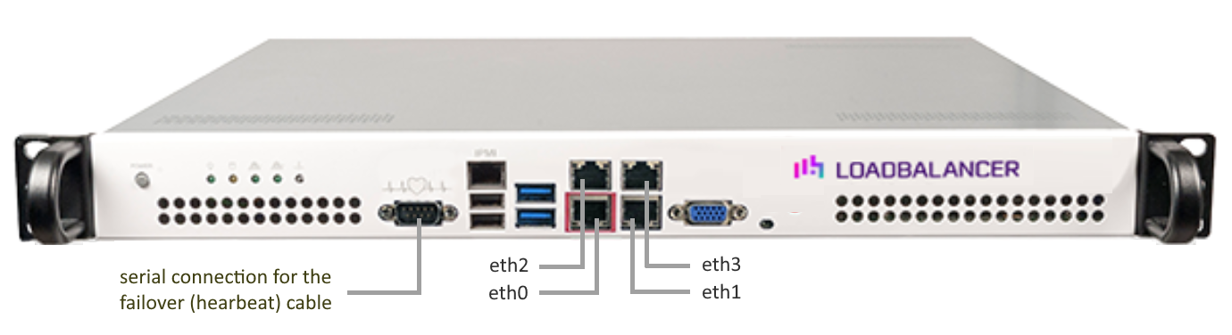
The above image shows the Enterprise Prime on Supermicro hardware. For network interface information for other models please refer to Front & Rear Panel Layouts. -
Now follow the on-screen instructions to configure the management IP address and other network settings as detailed in Configuring Initial Network Settings.
Virtual Appliance Installation
Supported Hypervisors
The VA is currently available for the following hypervisors:
-
VMware vSphere/ESXi : v6.0 & later
-
KVM : Kernel version v2.6.20 & later
Host Requirements
To run the Loadbalancer.org Endurance VA (irrespective of which Hypervisor is being used) the following basic server specifications must be met:
-
64bit CPU
-
Virtual Technology hardware support - either Intel-VT-x or AMD-V compliant CPUs
Virtual Hardware Resource Allocations
By default the appliance is allocated the following resources:
-
2 vCPUs
-
4 GB RAM
-
50GB drive
The CPU and memory allocations are suitable for a PoC or for low to medium throughput production applications. For more demanding situations, they can be increased as needed.
Resources required depend on multiple factors including the application being load balanced, the number of end-users, the anticipated throughput, the underlying physical hardware running the hypervisor and whether you’ll be load balancing at layer 4 or layer 7. Therefore it’s not realistic to make generic recommendations.
If you need assistance in determining the resources required for your deployment, please contact support.
Download & Extract the Appliance
-
Go to https://www.loadbalancer.org/get-started/adc-free-trial/.
-
Enter your details (all fields except email address are optional).
-
Click the Download button.
-
Now click the Download link next to the appropriate hypervisor.
-
Unzip the contents of the file to your chosen location.
| All information provided is 100% confidential. If you’re conducting a PoC (Proof of Concept) trial we may follow up with an email or phone call to see how you’re getting on and offer assistance, but under no circumstances will Loadbalancer.org share your details with a third party. |
| The same download is used for the licensed product, the only difference is that a license key file (supplied by our sales team when the product is purchased) must be applied using the appliance’s WebUI. |
Hypervisor Deployment
VMware vSphere Client
The steps below apply to VMware ESX/ESXi & vSphere Client v6.7 and later.
Upgrading to the latest Hardware Version
When the appliance is deployed, the virtual hardware version is set to 11. This enables compatibility with ESX version 6.0 and later. You can upgrade to a later hardware version if required.
| Create a snapshot or backup of the virtual machine first before upgrading. |
Installing the Appliance using vSphere Client
-
Right-click the inventory object where the appliance is to be located and select Deploy OVF Template.
-
In the Select an OVF Template screen, select the Local File option, click Browse, navigate to the download location, select both the .ovf and .vmdk files and click Next.
-
In the Select a name and folder screen, type a suitable name for the appliance - this can be up to 80 characters in length.
-
Select the required location for the appliance - by default this will be the location of the inventory object from where the wizard was started and click Next.
-
In the Select a compute resource screen, select the required compute resource for the appliance - by default this will be the inventory object from where the wizard was started and click Next.
-
In the Review details screen, verify the template details and click Next.
-
In the Select Storage screen, first select the required storage location for the appliance.
-
Now select the required disk format and click Next.
Loadbalancer.org recommends selecting a thick provision format. By default the appliance disk is 20GB. -
In the Select Networks screen, select the required destination network using the drop-down next to VM Network and click Next.
-
In the Ready to complete screen, review the settings and click Finish to create the virtual appliance. To change a setting, use the Back button to navigate back through the screens as required.
Configure Additional Network Adapters
The appliance has 4 network adapters. By default only the first adapter is connected. This will be eth0 when viewed in the appliance WebUI. If you require additional network adapters to be connected, follow the steps below:
-
Right-click the appliance, select Edit Settings.
-
Using the drop-down next to the relevant network adapter(s), select the required Network and tick (check) the Connected check-box and click OK.
XEN
The following steps should be followed on the XEN host:
-
Extract the archive.
-
Import the xva file into XEN.
KVM
The following steps should be followed on the KVM host:
-
Extract the archive to /var/lib/libvirt/images/.
-
virsh define Loadbalancer*.xml.
-
virsh start Loadbalancer*.
| Network cards are set to NAT by default so adjust as needed before powering on. Please also refer to the XML file for additional configuration notes. |
Configure Initial Network Settings
After power up, the following startup message is displayed on the appliance console:
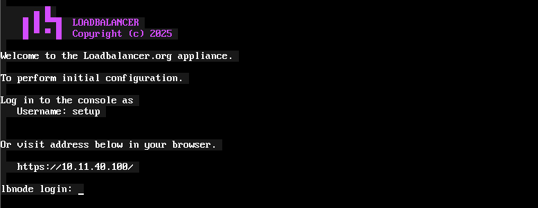
| If the welcome screen shown above does not appear, press CTRL-D. |
As mentioned in the text, initial network configuration can be performed at the console or via a browser. This will enable you to configure the management IP address and other network settings for the appliance.
At the Console
To start the console based setup process, login as the "setup" user. Once logged in, the Network Setup Wizard will start automatically.
Username: setup <Enter>
| A password is not required. |
A series of screens will be displayed that allow network settings to be configured:
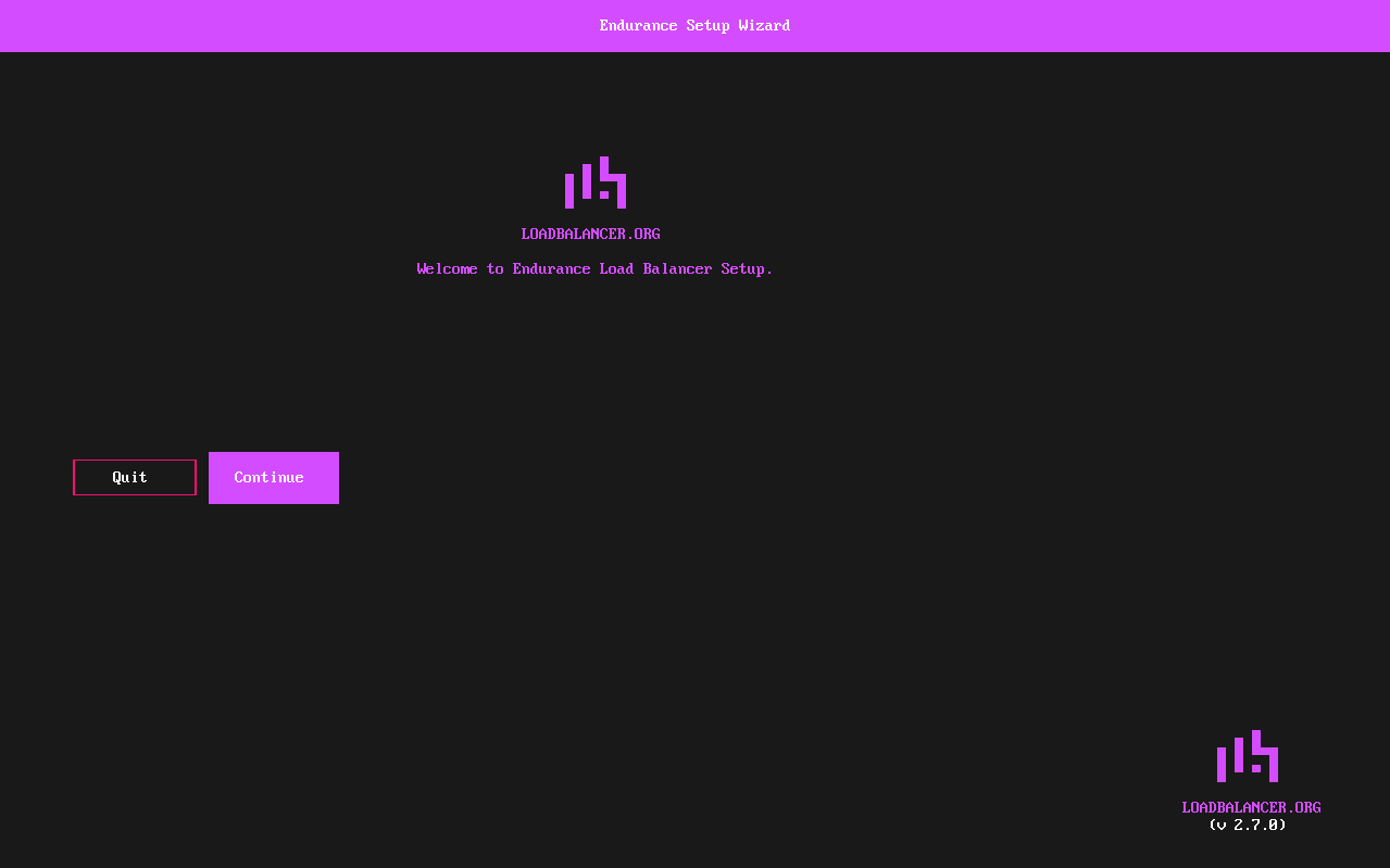
In the Welcome to Endurance screen, ensure Continue is selected and hit Enter to continue.
In the keymap screen, select the required keymap settings and hit Enter to continue.
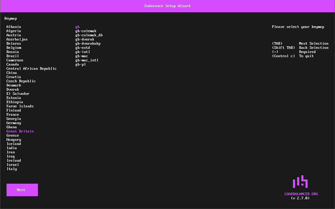
The Next button will be selected, hit Enter to continue.
In the Client Credentials screen, enter your Email and Password. These will be used to login to the appliance’s WebUI. Hit Enter to continue.
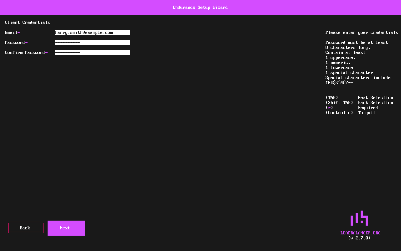
The Next button will be selected, hit Enter to continue.
In the Timezone screen, select the required timezone settings, and hit Enter to continue.
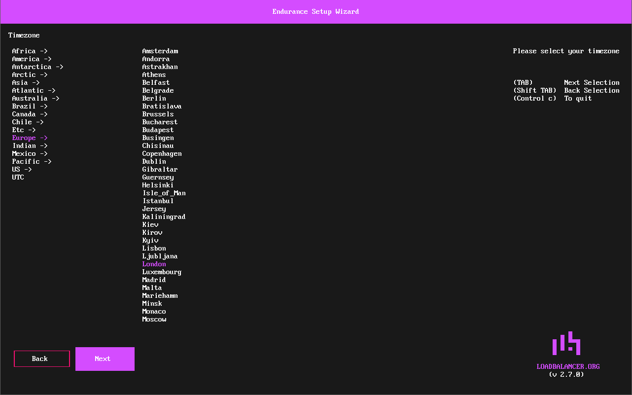
The Next button will be selected, hit Enter to continue.
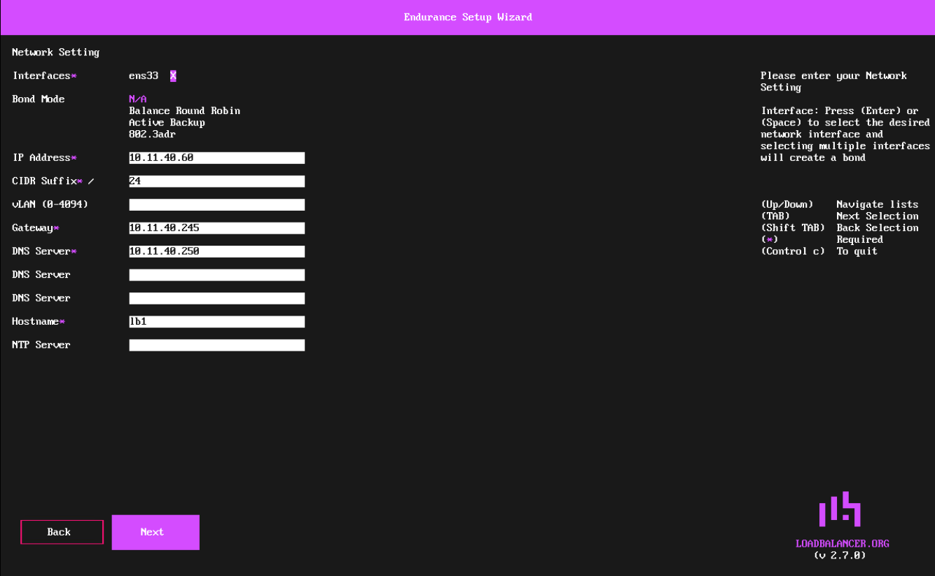
The Network Setting screen will be displayed.
| This screen is used to configure the management interface. Additional interfaces must be configured using the WebUI. |
-
Using the Spacebar, ensure that the Interface is selected.
-
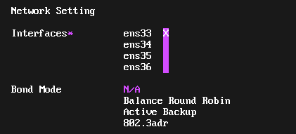
If additional adapters were added to the VA, additional interfaces will be displayed as shown below:
-
Select the required Interface(s). Multiple interfaces can be selected and bonded - in this case, select the required Bond Mode - the following options are available:
-
Balance Round Robin - This mode distributes network traffic across multiple network interfaces in a sequential, cyclic manner.
-
Active Backup - This mode places one of the adapters in a backup state and will only become active if the link is lost to the active adapter. This mode provides fault tolerance.
-
802.3ad - Dynamic link aggregation mode. This mode requires a switch that supports IEEE 802.3ad.
-
-
-
Set the required IP Address and CIDR Suffix.
A subnet mask such as 255.255.255.0 is not valid, in this case set the CIDR Suffix to 24. -
If required, set a VLAN ID.
-
Configure an appropriate Default Gateway, DNS Server and Hostname.
-
Hit Enter to continue.
The Next button will be selected, hit Enter to continue.
In the Summary screen, check all settings. If you need to change anything, use the Back button. If everything is correct, ensure that Confirm selected and hit Enter to continue.
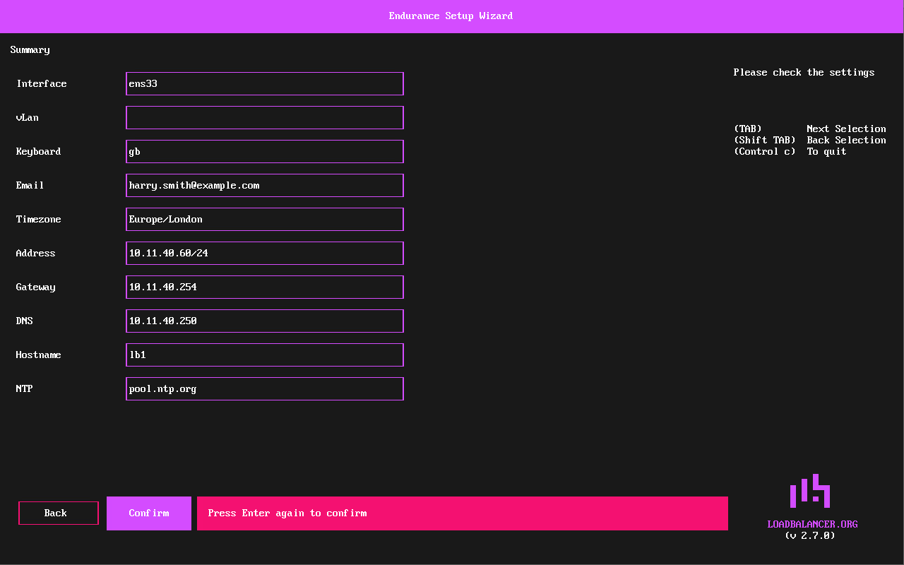
Hit Enter again to confirm. All settings will be applied.
Once the configuration has been written, the Setup Complete screen will be displayed.
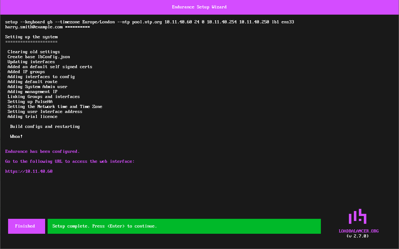
Hit Enter to exit the wizard and return to the command prompt.
Using a Browser
To start the web based setup process, browse to the IP address mentioned on the startup screen.
| Using the web based setup is only possible if a DHCP server is available which can provide a temporary IP address. |
In the keyboard screen, select the required keyboard settings.
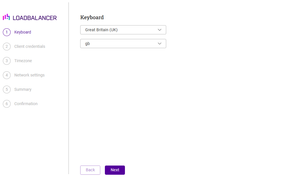
Click Next to continue.
In the Client Credentials screen, enter your Email and Password. These will be used to login to the appliance’s WebUI.
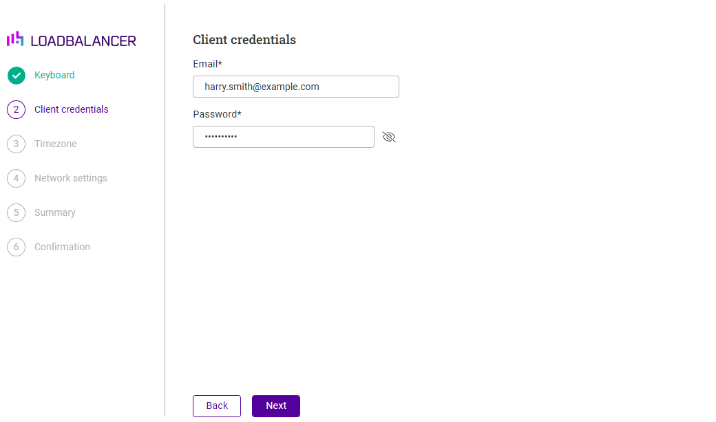
Click Next to continue.
In the Timezone screen, select the required timezone settings.
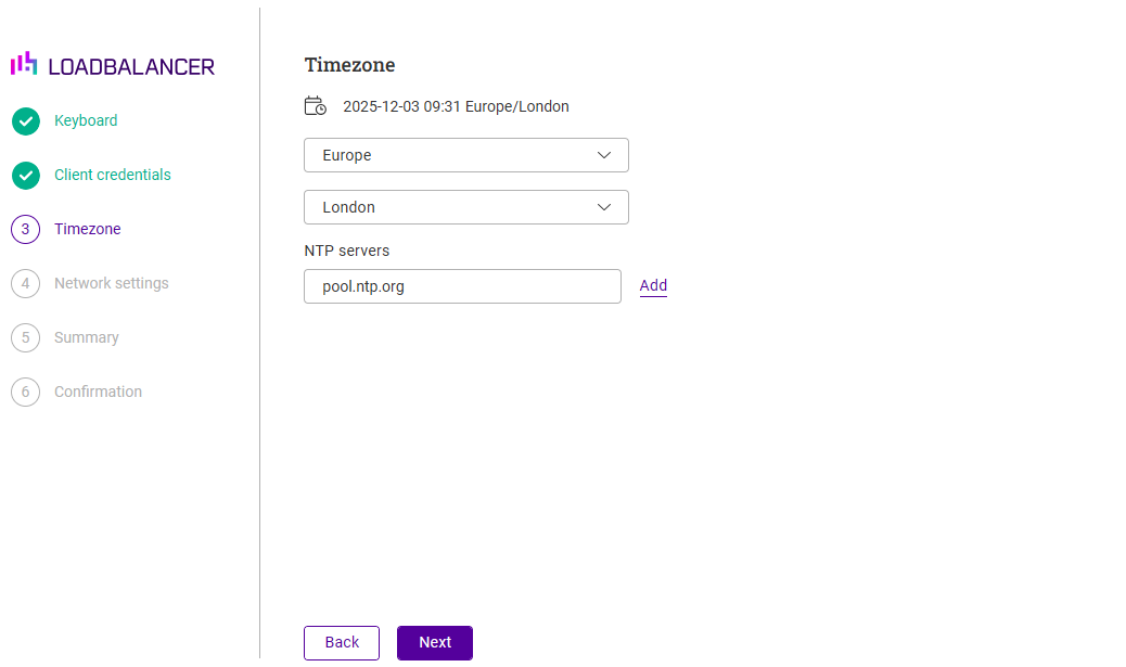
Click Next to continue.
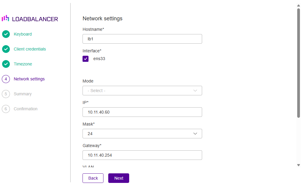
In the Network Settings screen, configure the required network settings.
| This screen is used to configure the management interface. Additional interfaces must be configured using the WebUI. |
-
Specify an appropriate Hostname.
-
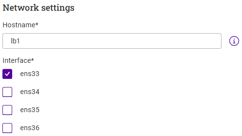
If additional adapters were added to the VA, additional interfaces will be displayed as shown below:
-
Select the required Interface(s). Multiple interfaces can be selected and bonded - in this case, select the required Bond Mode - the following options are available:
-
Balance Round Robin - This mode distributes network traffic across multiple network interfaces in a sequential, cyclic manner.
-
Active Backup - This mode places one of the adapters in a backup state and will only become active if the link is lost to the active adapter. This mode provides fault tolerance.
-
802.3ad - Dynamic link aggregation mode. This mode requires a switch that supports IEEE 802.3ad.
-
-
-
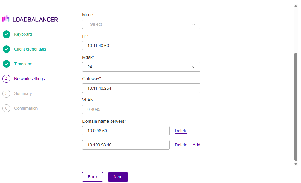
Set the required IP Address and select the required subnet Mask.
-
Configure an appropriate Default Gateway.
-
Scroll down to display the remaining fields.
-
If required, set a VLAN ID.
-
Configure the required Domain name servers.
Click Next to continue.
In the Summary screen, check all settings. If you need to change anything, use the Back button.
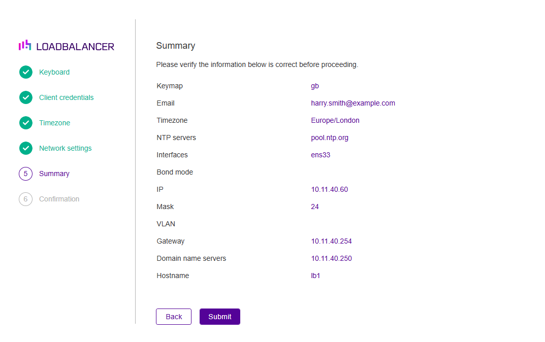
If everything is correct, click Submit.
Once the configuration has been written, the Confirmation screen will be displayed.
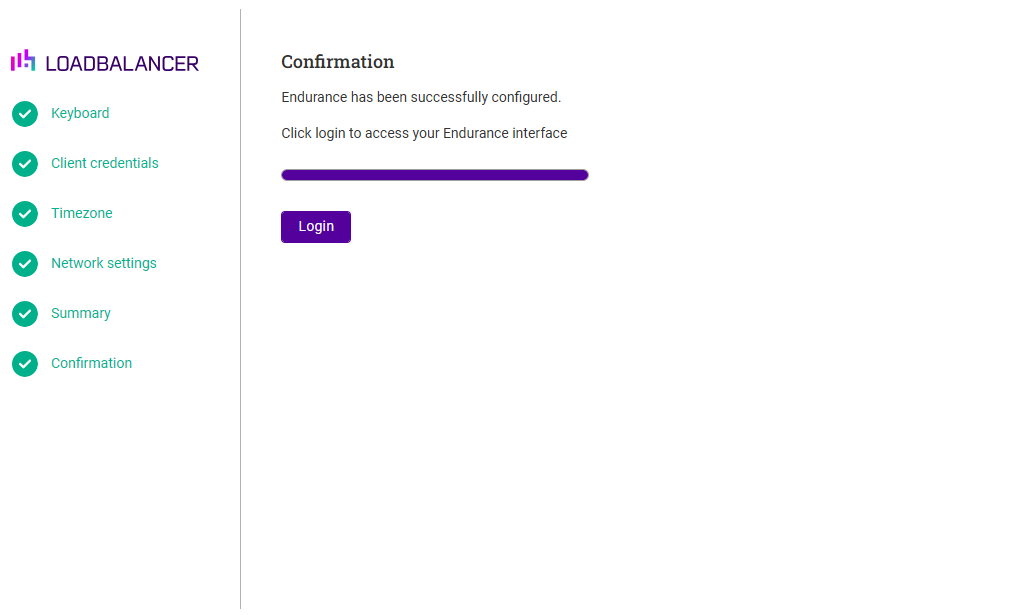
Click Login to open the WebUI login page for the appliance.
Accessing the Appliance WebUI
-
Using a browser, navigate to the following URL:
https://<IP-address-configured-during-the-network-setup-wizard>
You’ll receive a warning about the WebUI’s SSL certificate. This is due to the default self signed certificate that is used. If preferred, you can upload your own certificate. -
Log in to the WebUI using the following credentials:
Email: <configured-during-network-setup-wizard>
Password: <configured-during-network-setup-wizard>Once logged in, the WebUI will be displayed as shown below:
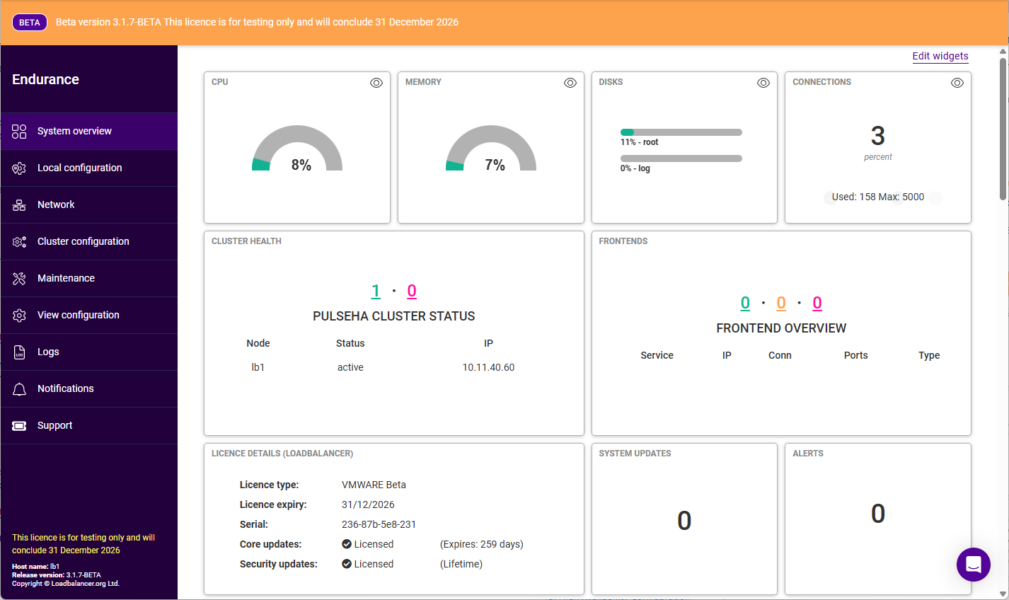
Menu Options
The main menu is comprised of a primary and secondary menu. By default, the primary menu is always open. This can be customised to suit your preferences under Maintenance > Account Settings.
The primary menu options are:
-
System Overview - Main system dashboard - includes key system information and summary of all load balanced services
-
Local Configuration - Configure local host settings such as data & time, WebUI settings and SNMP
-
Network - Configure network settings such as IP address, IP groups (subnets) DNS server(s)
-
Cluster Configuration - Configure load balanced services, SSL certificates, HA and health checks
-
Maintenance - Perform maintenance tasks such as backup and restore, service restarts and software updates
-
View Configuration - Display the on-disk configuration for all settings configured
-
Logs - View all system logs
-
Notifications - View all system notifications
-
Support - Create a support download, contact the support team & access useful resources