Cluster Configuration
Configure load balanced services — virtual services, real servers, health checks, and the methods behind them.
Manage services
Layer 4 Services
Introduction
Layer 4 Services are based on LVS (Linux Virtual Server). LVS implements transport layer load balancing inside the Linux kernel. It is used to direct requests for TCP/UDP based services to the Real Servers and makes services on the Real Servers appear as a Virtual Service on a single IP address.
With the exception of Layer 4 SNAT mode, Layer 4 services are transparent by default, i.e. the source IP address is maintained through the load balancer to the Real Servers.
Layer 4 persistence is based on source IP and is enabled by default. The time out is reset each time the client makes a connection, so a 5 minute persistence setting could last for hours if the client is active and regularly refreshes their connection.
Multiple ports can be specified, for example 80 & 443. In this case persistence is useful to ensure that clients hit the same backend server for both HTTP & HTTPS traffic and also to prevent the client having to renegotiate the SSL connection.
| It’s not possible to configure a Service on the same IP address as any of the network interfaces. This ensures Services can "float" (move) between nodes in HA mode. |
Adding Layer 4 Services
To add a new layer 4 Service:
-
Using the WebUI, navigate to Cluster Configuration > Manage Services and click Add Service.
-
Select the Layer 4 template.
-
Click Add Layer 4 Service.
-
To display all settings, change Default Mode to Advanced Mode.
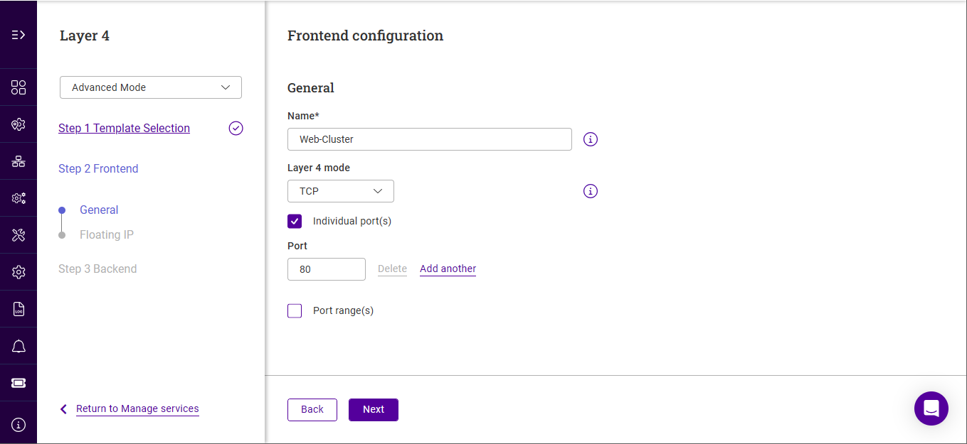
-
Specify a suitable name for the service, e.g. Web-Cluster.
-
Select the required Layer 4 mode, the options are:
Layer 4 mode Description TCP + UDP
Enable both TCP & UDP
TCP
Enable TCP only
UDP
Enable UDP only
One Packet Scheduling
Enable One Packet Scheduling - used for UDP SIP connections.
-
Specify the required port(s) using the Individual port(s) and Port range(s) options.
-
Click Next.
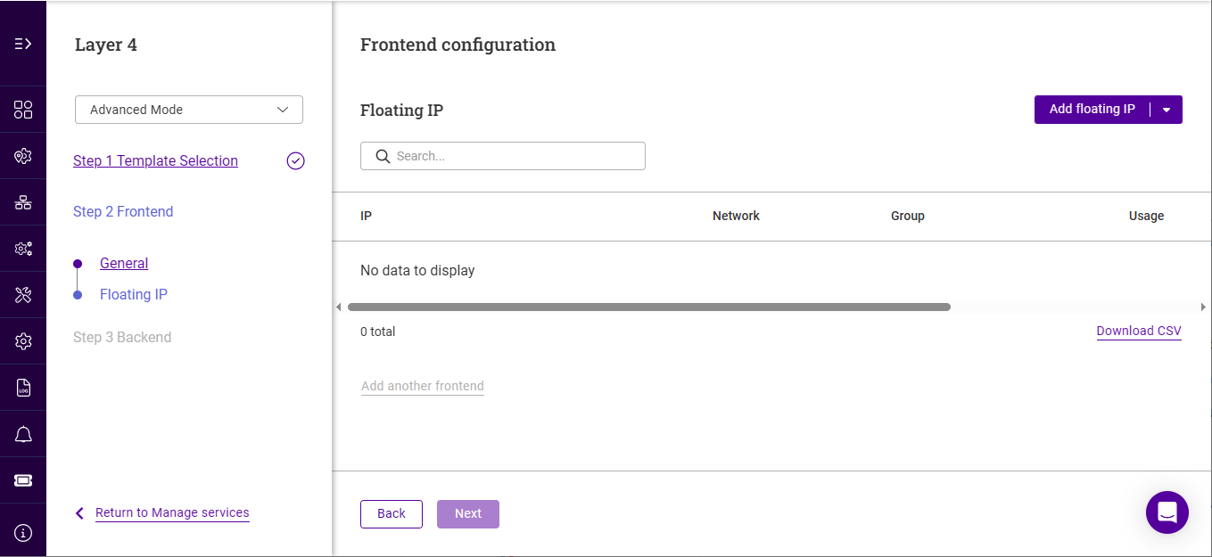
-
Specify the required Floating IP that the service should be associated with.
-
If the required address already exists, select the address.
-
If the required address does not exist, click Add floating IP.
-
Select the IP Group (subnet) where the Floating IP should be brought up.
For details on configuring IP groups please refer to XXXX. -
Specify a suitable IP address for the service, e.g. 10.11.45.125.
-
Click Add.
-
-
-
Ensure that the required Floating IP is selected and click Next.
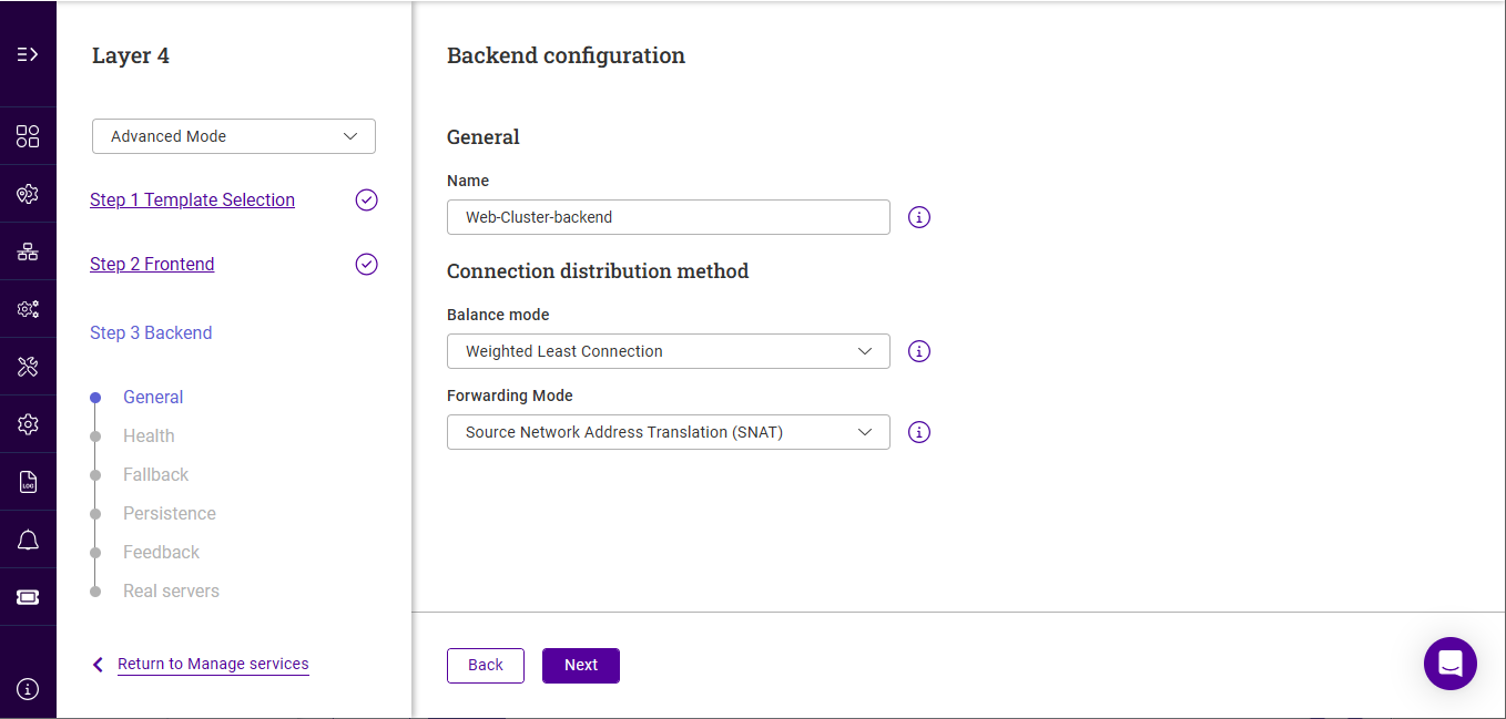
-
Specify a suitable Name, e.g. Web-Cluster-Backend.
-
Select the required Balance mode, the options are:
Balance mode Description Weighted Least-Connection
Assign more jobs to servers with fewer jobs, relative to the Real Server’s weight (default).
Weighted Round Robin
Assign jobs to Real Servers proportionally to the Real Server’s weight. Servers with higher weights receive new jobs first and get more jobs than servers with lower weights. Servers with equal weights receive an equal distribution of new jobs.
Destination Hash
Assign jobs to servers through looking up a statically assigned hash table by their destination IP addresses. This mode is designed for use with web proxies.
-
Specify the required Forwarding Mode, the options are:
Forwarding mode Description Source Network Address Translation (SNAT)
The mode requires no Real Server changes but is not as fast as DR mode. Also it’s non transparent and therefore looses the client source IP information.
Direct Routing
Requires the "ARP Problem" to be solved on each Real Server. For more information on DR mode, see Layer 4 DR Mode.
Destination Network Address Translation (DNAT)
Requires each Real Server to have its default gateway set as the load balancer.
Tunneling
Similar to DR mode but works across IP encapsulated tunnels
For full details of all modes, see XXXX. -
Click Next.
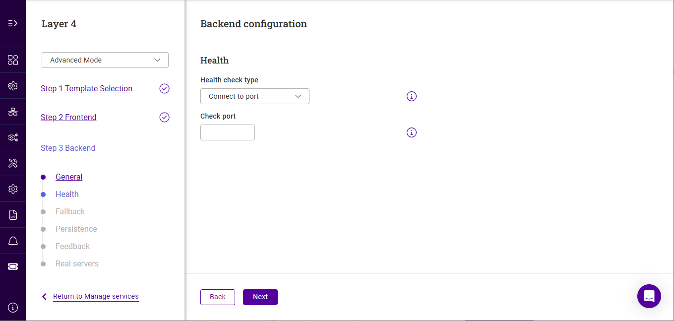
-
Specify the required Health check type and the associated settings, the options are:
Settings with (Adv) specified are only displayed in advanced mode. Health Check Type Description Settings Connect to port
Attempt to make a connection to the specified port
Check port (Adv) : the port to monitor. If specified this setting overrides the default which is the Real Server port. For multiport VIPs where the Real Server port field is left blank, the default check port is the first in the list. This can be changed using this field if required.
External script
Use a custom file for the health check
Check port (Adv) : See above.
External check script : Specify the script to use.For details on adding new health check scripts, see [XXXX]. Negotiate DNS
Perform a DNS check
Request to send : The file/page to open. This can also be the name of a server-side script that’s used to check the health of the backend application.
Response expected : The content expected in the specified file/page. The Response Expected can also be any valid regular expression statement. The result can be inverted by selecting "Not EqualsNegotiate FTP
Perform an FTP check
Check port (Adv) : See above
Username : Specify a username if authentication is required
Password : Specify a password if authentication is required
Request to send : See above
Response expected : See aboveNegotiate HTTP
Perform an HTTP check
Check port (Adv) : See above
Host Header : If the Real Server is configured to require a Host header, specify the value here
Request to send : See above
Response expected : See aboveNegotiate HTTP (Proxy)
Perform a Proxy check
Check port (Adv) : See above
Request to send : See above
Response expected : See aboveNegotiate HTTPS
Perform an HTTPS check
Check port (Adv) : See above
Request to send : See above
Response expected : See aboveNegotiate IMAP
Perform an IMAP check
Check port (Adv) : See above
Username : See above
Password : See aboveNegotiate IMAPS
Perform an IMAPS check
Check port (Adv) : See above
Username : See above
Password : See aboveNegotiate LDAP
Perform an LDAP check
Check port (Adv) : See above
Username : See above
Password : See aboveNegotiate MySQL
Perform an MySQL check
Check port (Adv) : See above
Database name : Specify the name of the MySQL database
Username : See above
Password : See above
Request to send : See aboveNegotiate NNTP
Perform an NNTP check
Check port (Adv) : See above
Negotiate POP
Perform a POP check
Check port (Adv) : See above
Username : As above
Password : As aboveNegotiate POPS
Perform a POPS check
Check port (Adv) : See above
Username : As above
Password : As aboveNegotiate RADIUS
Perform a RADIUS check
Check port (Adv) : See above
Radius Secret : Specify the Radius secret string
Username : As above
Password : As aboveNegotiate SMTP
Perform an SMTP check
Check port (Adv) : See above
No checks, always off
All Real Servers are marked offline
No health checks, all Real Servers are assumed to be down
No checks, always on
All Real Servers are marked online
No health checks, all Real Servers are assumed to be up
Ping Server
Use a simple ICMP ping to perform health checks
Sends an ICMP echo request packet to the Real Server
-
Click Next.
-
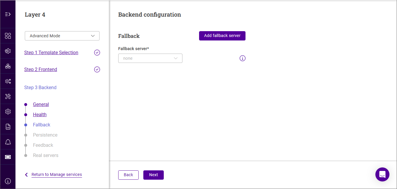
If required, specify the Fallback server.
-
If the fallback server already exists, select the server.
-
If the fallback server does not exist, click Add fallback server.
-
Specify a suitable Name.
-
Specify a Certificate if required.
-
Specify the Type.
-
If Internal is selected, specify the Page contents.
-
If External is selected, specify the IP address and Port of the fallback server.
-
-
-
Click Add.
-
-
Ensure the correct Fallback server is selected.
-
Select the required Forwarding Method for the fallback server.
-
Click Next.
-
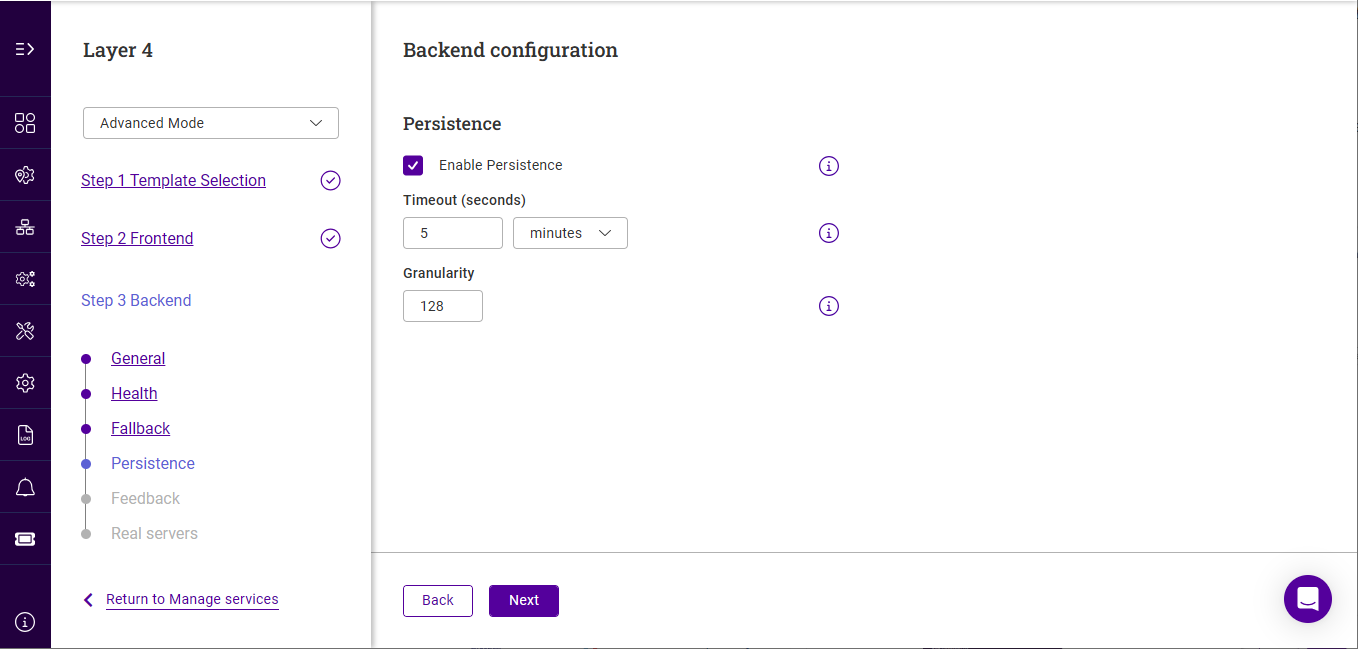
Use the Enable Persistence checkbox to enable/disable persistence. Persistent connections are required for some protocols such as FTP and SIP. It’s beneficial when using SSL to avoid re-negotiation and can be required with HTTP if your web application cannot keep state between Real Servers.
-
If enabled, set the required Timout. The timeout is reset on every new client connection.
-
If enabled, set the Granularity. The granularity level sets how many clients are grouped to a single Real Server. The default mask is 255.255.255.255 (or 128 for IPv6), meaning persistence is per individual client host, but less specific masks like 255.255.255.0 (or /24 for IPv6) can be used to direct all clients within a network to the same real server.
-
Click Next.
-
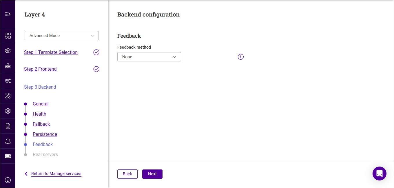
If required, configure the Feedback Method.
-
Select Agent to use utilise runtime data from the feedback agent installed on each Real Server.
-
Specify the Feedback Agent Port, the default in 3333.
-
-
Select HTTP to use any HTTP server responding on port 3333 to give feedback information to the load balancer.
-
-
Click Next.
-
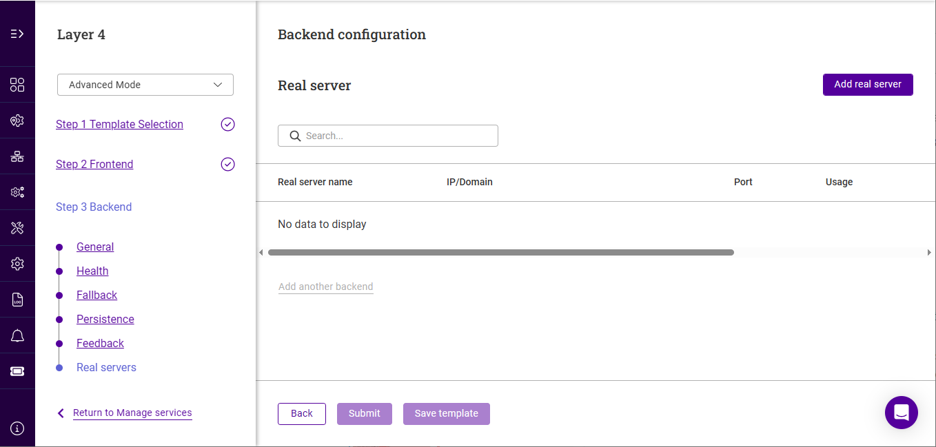
Click Add real server.
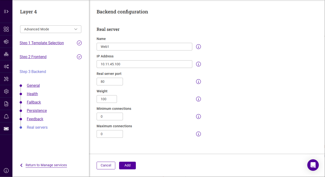
-
Specify a suitable Name, e.g. WEB1.
-
Specify the Real Server’s IP Address.
-
Specify the Real Server’s Port.
-
Specify the Real Server’s weight. This is an integer specifying the capacity of a server relative to the others in the pool, valid values are 0 to 65535, the default is 100. The higher the value, the more connections the server will receive. If the weight is set to 0, the server will effectively be placed in drain mode.
-
Specify the Real Server’s Minimum Connections. This is an integer specifying the lower connection threshold of a server. The valid values are 0 through to 65535. The default is 0, which means the lower connection threshold is not set. If set, the server will receive new connections when the number of its connections drops below its lower connection threshold. If not set but Maximum Connections is set, the server will receive new connections when the number of its connections drops below 3/4 of its upper connection threshold.
-
Specify the Real Server’s Maximum Connections. This is an integer specifying the upper connection threshold of a server. The valid values of Maximum Connections are 0 through to 65535. The default is 0, which means the upper connection threshold is not set.
-
Click Add.
-
Repeat these steps to add additional Real Servers.
-
Once all Real Servers have been added, click Submit to create the service.
Duplicating Layer 4 Services
If you have existing Layer 4 Services, these can be duplicated. During the duplication process, the name and the IP address and/or port must be changed so that it does not clash with the source Service.
To duplicate an existing layer 4 Service:
-
Click the three dots menu next to the Service you’d like to duplicate.
-
Click Duplicate.
-
Update the Name for the new Service.
-
Update the Port if required.
-
Click Next.
-
Update the Floating IP address if required.
At least one of these settings must be changed to ensure that the service can be created. -
Click Update.
DR Mode Considerations
The ARP Problem
DR mode works by changing the MAC address of the inbound packets to match the Real Server selected by the load balancing algorithm. To enable DR mode to operate:
-
The load balanced application/service/daemon running on each Real Server must be able to accept traffic destined for the VIP address and the Real Server’s own IP address (RIP). This is because in DR mode the destination address of load balanced packets is the VIP address, whilst for other traffic such as health checks, administration traffic etc. it’s the Real Server’s own IP address (the RIP).
-
Each Real Server must be configured so that it does not respond to ARP requests for the VIP address - only the load balancer should do this.
Configuring the Real Servers in this way is known as "Solving the ARP Problem". The steps required depend on the particular operating system being used.
Solving the ARP Problem for Linux
There are two different approaches on how to configure a Linux server for correct operation when DR mode load balancing is in use:
-
Modifying the server’s ARP behavior and adding the relevant VIP addresses to the loopback interface
-
Using NAT to convince the server to accept and reply to packets addressed to the relevant VIP addresses
Four independent methods are described below along with instructions. Each method follows one of the two approaches above. The specific method chosen will depend on technical requirements, the Linux distribution in use, and personal preferences.
The first method involves setting kernel parameters to alter the server’s ARP behavior and adding IP addresses to the loopback interface. This method should be universally applicable to any Linux server making this the preferred method.
If setting kernel parameters and adding IP addresses is not possible for some reason, the remaining three methods describe setting up a server for DR mode operation by using NAT via the redirect target/statement. The specific instructions depend on the packet filtering framework and tooling in use, which varies between Linux distributions. Methods are presented for iptables, nftables, and the firewall-cmd tool.
Method 1: ARP Behavior and Loopback Interface Changes
This is the preferred method as it should be applicable to any Linux server and doesn’t require any additional packet filtering or NAT considerations.
Each real server needs the loopback interface to be configured with the virtual IP addresses (VIPs) of the relevant load balanced services. This is often just a single VIP address, but the logic described below can be extended to cover multiple VIPs on a server. Having the VIPs on the loopback interface allows the server to accept inbound load balanced packets that are addressed to a VIP.
The server must not respond to ARP requests for the VIP addresses. The server also must not use ARP to announce the fact that it owns the VIP addresses. This is necessary to prevent IP address conflicts, as all of the real servers and the load balancer will own the VIP addresses. Only the load balancer should announce ownership of the VIPs.
To configure the behavior described above, follow all of the steps below on each real server.
This step is only applicable if IPv4-based virtual services are in use.
Add the following lines to the file /etc/sysctl.conf (create this file if it does not already exist):
net.ipv4.conf.all.arp_ignore=1
net.ipv4.conf.eth0.arp_ignore=1
net.ipv4.conf.eth1.arp_ignore=1
net.ipv4.conf.all.arp_announce=2
net.ipv4.conf.eth0.arp_announce=2
net.ipv4.conf.eth1.arp_announce=2
Adjust the commands shown above to suit the server’s network configuration, e.g. a different number of network interfaces or a different interface naming convention.
For Linux distros such as Debian 12+, Ubuntu 24.10+ and OpenSUSE that are using systemd and are running systemd-sysctl, /usr/lib/sysctl.d/50-default.conf should be modified rather than /etc/sysctl.conf.
|
|
For reference, the effect of these kernel parameter changes on the server is as follows:
|
This step is only applicable if IPv6-based virtual services are in use.
Add the following lines to the file /etc/sysctl.conf (create this file if it does not already exist):
net.ipv6.conf.lo.dad_transmits=0
net.ipv6.conf.lo.accept_dad=0
For Linux distros such as Debian 12+, Ubuntu 24.10+ and OpenSUSE that are using systemd and are running systemd-sysctl, /usr/lib/sysctl.d/50-default.conf should be modified rather than /etc/sysctl.conf.
|
|
For reference, the effect of these kernel parameter changes on the server is as follows:
|
To apply the new settings, either reboot the real server or execute the following command to immediately apply the changes:
/sbin/sysctl -p
|
Steps 1, 2, and 3 can be replaced by instead modifying the necessary kernel variables by writing directly to their corresponding files under Execute the following commands (as root) to implement these temporary changes (adapting the number of interfaces and interface names as needed): echo 1 > /proc/sys/net/ipv4/conf/all/arp_ignore echo 1 > /proc/sys/net/ipv4/conf/eth0/arp_ignore echo 1 > /proc/sys/net/ipv4/conf/eth1/arp_ignore echo 2 > /proc/sys/net/ipv4/conf/all/arp_announce echo 2 > /proc/sys/net/ipv4/conf/eth0/arp_announce echo 2 > /proc/sys/net/ipv4/conf/eth1/arp_announce echo 0 > /proc/sys/net/ipv6/conf/lo/dad_transmits echo 0 > /proc/sys/net/ipv6/conf/lo/accept_dad |
Each of the VIP addresses must be permanently added to the loopback interface. VIPs must be added with a network prefix of /32 for IPv4 addresses or /128 for IPv6 addresses. The IP addresses can be added using the usual configuration files and tools for modifying network interfaces, which vary between different Linux distributions.
As an alternative, the ip command can be used as a universal way to add IP addresses to any Linux server. Note that addresses added in this way will not persist across reboots. To make these addresses permanent, add the ip commands to an appropriate startup script such as /etc/rc.local.
Execute the following ip command for each IPv4 VIP:
ip addr add dev lo <IPv4-VIP>/32
Execute the following ip command for each IPv6 VIP:
ip addr add dev lo <IPv6-VIP>/128
To check that the VIPs have been successfully added, execute the command:
ip addr ls
To remove an IPv4 VIP from the loopback adapter, execute the command:
ip addr del dev lo <IPv4-VIP>/32
To remove an IPv6 VIP from the loopback adapter, execute the command:
ip addr del dev lo <IPv6-VIP>/128
Method 2: NAT "redirect" via iptables
iptables can be used on each real server to identify incoming packets that are addressed to a virtual IP address (VIP) and redirect those packets to the server itself. This is achieved using the REDIRECT target in iptables, which performs the necessary NAT to make this possible. This allows a real server to accept packets addressed to a VIP without the server owning the VIP.
Execute the following command to put the necessary iptables rule in place to redirect traffic for a single IPv4 VIP address. Note that iptables rules added in this way will not persist across reboots. To make such a rule permanent, either add the rule to an iptables firewall script, if one is provided with the Linux distribution in question, or add the command to an appropriate startup script such as /etc/rc.local on each real server.
iptables -t nat -A PREROUTING -d <IPv4-VIP> -j REDIRECT
The VIP address should be changed to match the virtual service in question, for example:
iptables -t nat -A PREROUTING -d 10.0.0.21 -j REDIRECT
The example above will redirect any incoming packets destined for 10.0.0.21 (the virtual service) locally, i.e. to the primary address of the incoming interface on the real server.
If a real server is responsible for serving multiple VIPs then additional iptables rules should be added to cover each VIP.
For an IPv6 VIP address, a command like the following should be used:
ip6tables -t nat -A PREROUTING -d <IPv6-VIP> -j REDIRECT
The VIP address should be changed to match the virtual service in question, for example:
ip6tables -t nat -A PREROUTING -d 2001:db8::10 -j REDIRECT
| Method 2 may not be appropriate when using IP-based virtual hosting on a web server. This is because an iptables REDIRECT rule will redirect incoming packets to the primary address of the incoming interface on the web server rather than any of the virtual hosts that are configured. Where this is an issue, use method 1 instead. |
Method 3: NAT "redirect" via nftables
nftables is the modern Linux kernel packet filtering framework. It is supported on all major Linux distributions and has replaced iptables as the default framework on most major distributions.
nftables can be used on each real server to identify incoming packets that are addressed to a virtual IP address (VIP) and redirect those packets to the server itself. This is achieved using the redirect statement in nftables, which performs the necessary NAT to make this possible. This allows a real server to accept packets addressed to a VIP without the server owning the VIP.
Use a script like the following to put the necessary nftables structures in place to redirect traffic for both IPv4 and IPv6 VIP addresses. To make such a configuration permanent, either add the inet nat table to an nftables firewall script, if one is provided with the Linux distribution in question, or configure a script like the following to execute as a startup script on each real server.
#!/usr/sbin/nft -f

table inet nat {
    chain prerouting {
        comment "Allow server to accept packets destined for VIP addresses";
        type nat hook prerouting priority -100; policy accept;
        ip daddr <IPv4-VIP> redirect comment "Description"
        ip6 daddr <IPv6-VIP> redirect comment "Description"
    }
}
The VIP addresses and comments should be changed to match the virtual services in question, for example:
#!/usr/sbin/nft -f

table inet nat {
    chain prerouting {
        comment "Allow server to accept packets destined for VIP addresses";
        type nat hook prerouting priority -100; policy accept;
        ip daddr 10.0.0.21 redirect comment "VIP 1: HTTP"
        ip6 daddr 2001:db8::10 redirect comment "VIP 2: HTTPS"
    }
}
The example above will redirect any incoming packets destined for 10.0.0.21 or 2001:db8::10 (the virtual services) locally, i.e. to the primary address of the incoming interface (for each IP version) on the real server.
Note that Linux kernels prior to 5.2 may not support performing NAT (which is required for the redirect statement) in an inet family table. In this scenario, use either an ip or an ip6 family table instead, or both if a mixture of IPv4 and IPv6 VIPs are in use on the same server. Also note that older kernels may not support the use of comments in chains.
Note that Linux kernels prior to 4.18 require explicitly registering both prerouting and postrouting chains in order for the implicit NAT of the redirect statement to be correctly performed in both the inbound and outbound directions.
A legacy-friendly setup may look like the following:
#!/usr/sbin/nft -f

table ip nat {
    chain prerouting {
        type nat hook prerouting priority -100; policy accept;
        ip daddr 10.0.0.21 counter redirect comment "VIP 1: HTTP"
    }

    chain postrouting {
        type nat hook postrouting priority 100; policy accept;
    }
}

table ip6 nat {
    chain prerouting {
        type nat hook prerouting priority -100; policy accept;
        ip6 daddr 2001:db8::10 counter redirect comment "VIP 2: HTTPS"
    }

    chain postrouting {
        type nat hook postrouting priority 100; policy accept;
    }
}
| Method 3 may not be appropriate when using IP-based virtual hosting on a web server. This is because an nftables redirect statement will redirect incoming packets to the primary address of the incoming interface on the web server rather than any of the virtual hosts that are configured. Where this is an issue, use method 1 instead. |
Method 4: NAT "redirect" via firewall-cmd
Some recent versions of Linux distributions make use of firewalld as a high-level firewall configuration framework. In this case, while it may actually be iptables performing the work at a lower level, it may be preferred to implement the iptables NAT solution described in method 2 in firewalld, as opposed to directly manipulating iptables. This is achieved by using the firewall-cmd tool provided by firewalld and executing a command like the following on each real server:
firewall-cmd --permanent --direct --add-rule ipv4 nat PREROUTING 0 -d <IPv4-VIP> -j REDIRECT
The VIP address should be changed to match the virtual service in question, for example:
firewall-cmd --permanent --direct --add-rule ipv4 nat PREROUTING 0 -d 10.0.0.50 -j REDIRECT
To apply the new configuration, reload the firewall rules like so:
firewall-cmd --reload
Configuration applied in this way will be permanent and will persist across reboots.
| Method 4 may not be appropriate when using IP-based virtual hosting on a web server. This is because an iptables REDIRECT rule will redirect incoming packets to the primary address of the incoming interface on the web server rather than any of the virtual hosts that are configured. Where this is an issue, use method 1 instead. |
Solving the ARP Problem for Solaris
For Solaris v11 and later, run the following command on each Real Server:
ipadm create-addr -a <VIP>/32 lo0
The configuration survives a reboot so there’s no need to add this command to a startup script.
Solving the ARP Problem for Mac OS X/BSD
OS X is BSDish, so you need to use BSDish syntax:
ifconfig lo0 alias <VIP> netmask 255.255.255.255 -arp up
You’ll need to add this to the startup scripts on all of your Real Servers.
| Don’t forget that the service on the Real Servers needs to listen on both the RIP address and VIP address as mentioned previously. |
| Failure to correctly configure the Real Servers to handle the "ARP Problem" is the most common issue when using DR mode. |
Solving the ARP Problem for Windows Servers
Windows Server 2012 & Later
Windows Server 2012 and later support Direct Routing (DR) mode through the use of the Microsoft Loopback Adapter that must be installed and configured on each load balanced (Real) Server. The IP address configured on the Loopback Adapter must be the same as the Virtual Service (VIP) address. This enables the server to receive packets that have their destination set as the VIP address. If a Real Server is included in multiple DR mode VIPs, an IP address for each VIP must be added to the Loopback Adapter.
In addition, the strong/weak host behavior must be configured on each Real Server. The weak host model allows packets with any IP to be sent or received via an interface. The strong host model only allows packets with an IP belonging to the interface to be sent or received.
| The following 3 steps must be completed on all Real Servers associated with the VIP. |
-
Click Start, then run hdwwiz to start the Hardware Installation Wizard.
-
Once the Wizard has started, click Next.
-
Select Install the hardware that I manually select from a list (Advanced), click Next.
-
Select Network adapters, click Next.
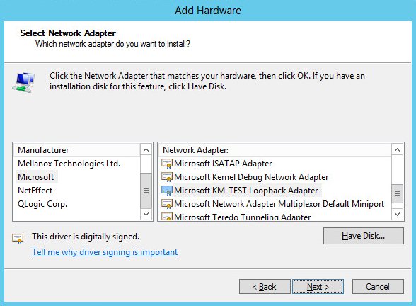
-
Select Microsoft & Microsoft KM-Test Loopback Adapter, click Next.
-
Click Next to start the installation, when complete click Finish.
-
Open Control Panel and click Network and Sharing Center.
-
Click Change adapter settings.
-
Right-click the new Loopback Adapter and select Properties.
| You can configure IPv4 or IPv6 addresses or both depending on your requirements. |
IPv4 Addresses
-
Uncheck all items except Internet Protocol Version 4 (TCP/IPv4) as shown below:
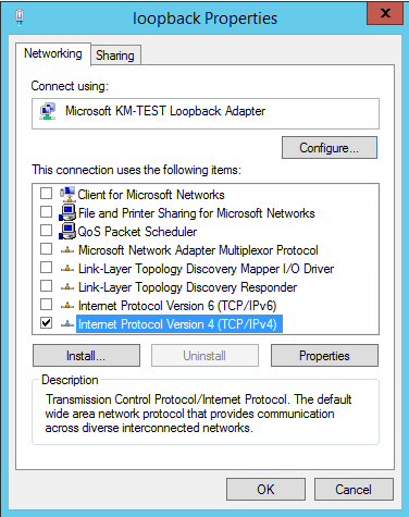
-
Ensure that Internet Protocol Version (TCP/IPv4) is selected, click Properties and configure the IP address to be the same as the Virtual Service address (VIP) with a subnet mask of 255.255.255.255, e.g. 192.168.2.20/255.255.255.255 as shown below:
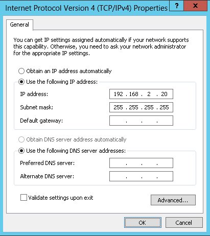
192.168.2.20 is an example, make sure you specify the correct VIP address. If a Real Server is included in multiple DR mode VIPs, an IP address for each VIP must be added to the Loopback Adapter. -
Click OK then click Close to save and apply the new settings.
IPv6 Addresses
-
Uncheck all items except Internet Protocol Version 6 (TCP/IPv6) as shown below:
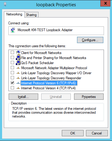
-
Ensure that Internet Protocol Version (TCP/IPv6) is selected, click Properties and configure the IP address to be the same as the Virtual Service (VIP) and set the Subnet Prefix Length to be the same as your network setting, e.g. 2001:470:1f09:e72::15/64 as shown below:
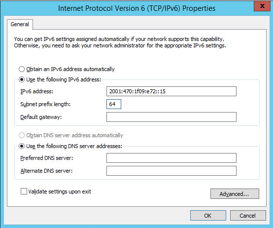
2001:470:1f09:e72::15/64 is an example, make sure you specify the correct VIP address. If a Real Server is included in multiple DR mode VIPs, an IP address for each VIP must be added to the Loopback Adapter. -
Click OK then click Close to save and apply the new settings.
The strong/weak host behavior can be configured using either of the following 2 methods:
-
Option 1 - Using network shell (netsh) commands
-
Option 2 - Using PowerShell cmdlets
The commands in this section assume that the LAN Adapter is named "net" and the Loopback Adapter is named "loopback" as shown in the example below:
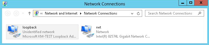
|
Either adjust the commands to use the names allocated to your LAN and loopback adapters, or rename the adapters before running the commands. Names are case sensitive so make sure that the interface names used in the commands match the adapter names exactly. |
Option 1 - Using Network Shell (netsh) Commands
To configure the correct strong/weak host behavior run the following commands:
For IPv4 addresses:
netsh interface ipv4 set interface "net" weakhostreceive=enabled
netsh interface ipv4 set interface "loopback" weakhostreceive=enabled
netsh interface ipv4 set interface "loopback" weakhostsend=enabled
For IPv6 addresses:
netsh interface ipv6 set interface "net" weakhostreceive=enabled
netsh interface ipv6 set interface "loopback" weakhostreceive=enabled
netsh interface ipv6 set interface "loopback" weakhostsend=enabled
netsh interface ipv6 set interface "loopback" dadtransmits=0
Option 2 - Using PowerShell Cmdlets
For IPv4 addresses:
Set-NetIpInterface -InterfaceAlias loopback -WeakHostReceive enabled -WeakHostSend enabled -AddressFamily IPv4
Set-NetIpInterface -InterfaceAlias net -WeakHostReceive enabled -AddressFamily IPv4
For IPv6 Addresses:
Set-NetIpInterface -InterfaceAlias loopback -WeakHostReceive enabled -WeakHostSend enabled -DadTransmits 0 -AddressFamily IPv6
Set-NetIpInterface -InterfaceAlias net -WeakHostReceive enabled -AddressFamily IPv6
The following PowerShell Cmdlets can be used to verify the settings:
The "net" interface:
netsh interface ipv4 show interface net
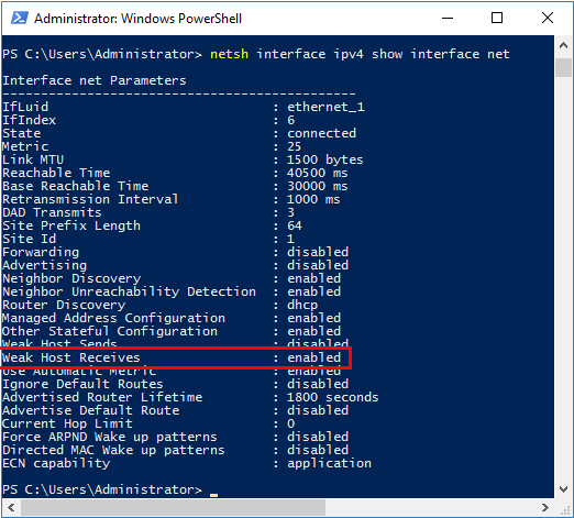
The "loopback" interface:
netsh interface ipv4 show interface loopback
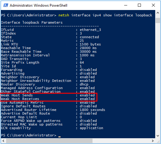
| For IPv6, replace "ipv4" with "ipv6" in the above commands. |
For Windows 2012 & later you can also use the following PowerShell Cmdlets to verify the settings:
To view both IPv4 and IPv6:
Get-NetIpInterface -InterfaceAlias loopback | FL
for IPv4 only:
Get-NetIpInterface -InterfaceAlias loopback -AddressFamily IPv4 | FL
for IPv6 only:
Get-NetIpInterface -InterfaceAlias loopback -AddressFamily IPv6 | FL
| Failure to correctly configure the Real Servers to handle the "ARP Problem" is the most common issue when using DR mode. |
Solving the ARP Problem - Possible Side Effect for Windows 2012 & Later
With DR Mode, the source IP address of return traffic from a Real Server will be the IP address assigned to the loopback adapter, which is the same as the VIP address that the client connected to. For traffic initiated by a Real Server, the source IP address should under normal circumstances be the Real Server’s own IP address, i.e. the address assigned to the standard network adapter.
However, due to the way the network adapters are configured to solve the "ARP Problem", and the way that Windows selects the source IP address, it’s possible under certain circumstances for the source IP address of traffic initiated by a Real Server to be the IP address configured on the loopback adapter rather than the Real Server’s own IP address. Please refer to this Microsoft article for more information on how Windows selects the source IP address.
To prevent the IP address(es) assigned to the loopback adapter being used in this way, the skipassource flag must be set for each IP assigned to the loopback adapter.
To check the current skipassource setting for all IPs associated with the loopback adapter, use the following command:
Get-NetAdapter -name loopback | Get-NetIPAddress | select ipaddress, skipassource
-
If your loopback adapter is not named "loopback" modify the command accordingly
Example output:
ipaddress       skipassource
---------       ------------
192.168.111.180        false
This shows that for the 192.168.111.180 address, the skipassource flag is not set.
To set the skipassource flag for the 192.168.111.180 address, use the following command:
Set-NetIPAddress –IPAddress 192.168.111.180 –SkipAsSource $True
To clear the skipassource flag for the 192.168.111.180 address, use the following command:
Set-NetIPAddress –IPAddress 192.168.111.180 –SkipAsSource $False
To set the skipassource flag for all IP addresses associated with the loopback adapter, the following two PowerShell commands can be used:
[array]$IPs = Get-NetIPAddress -InterfaceAlias loopback
Set-NetIPAddress -IPAddress $IPs.IPAddress -InterfaceAlias loopback -SkipAsSource $true
-
The first command gathers all IP addresses assigned to the loopback adapter
-
The second command then sets the SkipAsSource flag for all IPs found
-
If your loopback adapter is not named "loopback" modify the commands accordingly
| Make the sure that the same settings are configured on all Real Servers. |
Other Windows Settings that May Cause Issues
Receive Segment Coalescing (RSC)
RSC is a stateless offload technology that helps reduce CPU utilization for network processing on the receive side by offloading tasks from the CPU to an RSC-capable network adapter. In rare cases it has been discovered that RSC can adversely effect performance when using DR mode. In these cases the performance issue was addressed by disabling RSC.
To check the current RSC settings for all RSC compatible interfaces, use the following command:
Get-NetAdapterRsc
Example output:
Name  IPv4Enabled  IPv6Enabled  IPv4Operational IPv6Operational IPv4FailureReason IPv6FailureReason
                                State           State
----  -----------  -----------  --------------- --------------- ----------------- -----------------
net   True         True         True            True            NoFailure         NoFailure
-
In this example IPv4Operational State and IPv6Operational State are set to True which shows that RSC is enabled for both IPv4 and IPv6
RSC can be disabled and enabled using the GUI or by using PowerShell commands.
Using the GUI
RSC for IPv4 (Recv Segment Coalescing (IPv4)) and for IPv6 (Recv Segment Coalescing (IPv6)) can be configured using the NIC’s advanced properties tab as shown in the example below:
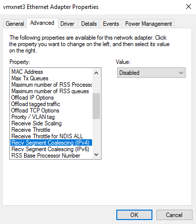
To access the adapter’s advanced properties using Windows 2016 (other versions may be slightly different) go to: Start > Settings > Network and Internet > Change adapter options, right click the adapter, select Properties, click Configure and then select the Advanced tab.
Using PowerShell
To disable RSC:
Disable-NetAdapterRsc -Name "net" -IPv4

or for IPv6

Disable-NetAdapterRsc -Name "net" -IPv6
To enable RSC:
Enable-NetAdapterRsc -Name "net" -IPv4

or for IPv6

Enable-NetAdapterRsc -Name "net" -IPv6
-
If your network adapter is not named "net" modify the command accordingly
Configuring Your Application to Respond to Both the RIP and VIP
For DR & TUN modes, it’s important to make sure that your application (IIS in this example) responds to both the VIP and RIP.
By default, IIS listens on all configured IP addresses as shown in the example below. As can be seen, the IP address field is set to "All Unassigned".
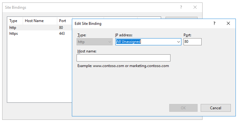
If the default setting is not changed, no further IIS configuration is required. If you do change the IP address in the bindings from "All Unassigned" to a specific IP address, then you need to make sure that you also add a binding for the Virtual Service IP address (VIP) as shown in the example below:
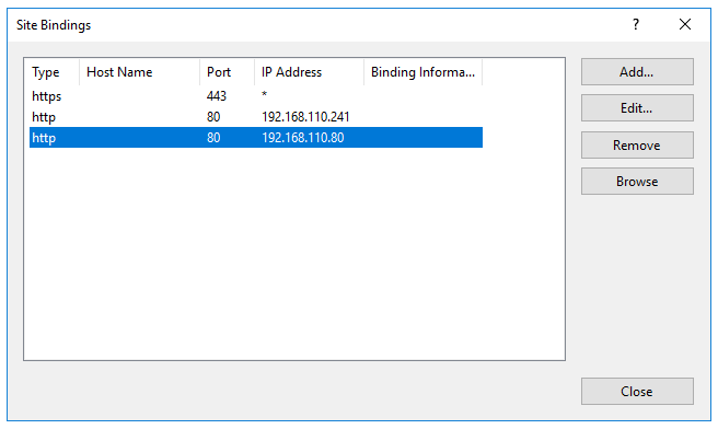
| This example illustrates how IIS must be configured to ensure that it’s listening on both the RIP and VIP address. Remember that this applies to ALL applications when using DR mode. |
Windows Firewall Settings
When IIS is installed, default rules are created that allow inbound traffic on port 80 and 443. By default, these rules apply to the Domain, Public and Private profiles and all interface types. If the rules are changed, make sure that inbound traffic can still reach both the LAN interface and the loopback adapter.
NAT Mode Considerations
Layer 4 NAT mode requires Real Server return traffic to pass back via the load balancer. This is achieved by setting each Real Server’s default gateway to be the load balancer. For an HA Pair, a floating IP address should be used to allow the gateway to "float" (move) between appliances should a failover occur.
Whilst NAT mode is fairly straight forward, certain points need to be considered.
NAT Mode Potential Issues
-
By default the Real Servers won’t be able to access the Internet through the new default gateway (except when replying to requests made through the external VIP).
-
Non-load balanced services on the Real Servers (e.g. RDP for management access to Windows servers) will not be accessible since these have not been exposed via the load balancer.
Enabling Access to non Load Balanced Services
If you want non load balanced services on your Real Servers to be accessible from the external subnet, options include:
-
Configure a SNAT mode Virtual Service listening on the relevant service port(s) and add the required Real Server leaving the Real Server Port field blank.
-
Configure a DNAT mode Virtual Service listening on the relevant service port(s) and add the required Real Server leaving the Real Server Port field blank. The Real Server’s default gateway must be the load balancer.
One-Arm (Single Subnet) NAT Mode
Normally the VIP is located on a different subnet to the Real Servers. However, it is possible to perform NAT mode load balancing on a single subnet where the VIP is brought up in the same subnet as the Real Servers. For clients located on this subnet, return traffic would normally be sent directly to the client bypassing the load balancer which would break NAT mode. To address this, the routing table on the Real Servers must be modified to force return traffic to pass via the load balancer. The sections below explain how routing must be modified for Windows hosts and Linux hosts.
Route Configuration for Windows Servers
To rectify this issue for Windows servers, a route must be added to each Real Server that takes priority over the default Windows routing rules. This is a simple case of deleting the default On-link route and adding a permanent route via the load balancer using the following commands on each real server:
netsh interface ipv4 delete route 192.168.2.0/24 "LAN"
netsh interface ipv4 add route 192.168.2.0/24 "LAN" 192.168.2.21
| Replace "192.168.2.0/24" with your subnet address, "192.168.2.21" with your load balancer’s IP address and "LAN" with the name of the interface on your server. |
| After running the above commands, reboot the server and check if the updated routing rules have remained. Depending on the specific version of Windows, it may be necessary to add the commands to a startup script. This is because under certain circumstances routing rules for on-link, directly accessible addresses can get reset to defaults after a reboot. |
Verify routing rules using the following command:
netsh interface ipv4 show route
Route Configuration for Linux Servers
To rectify this issue for Linux servers, the local network route must be changed to a higher metric:
route del -net 192.168.2.0 netmask 255.255.255.0 dev eth0
route add -net 192.168.2.0 netmask 255.255.255.0 metric 2000 dev eth0
| Ensure you specify your local subnet address. |
Then we must ensure that local network access uses the load balancer as its default route:
route add -net 192.168.2.0 netmask 255.255.255.0 gateway 192.168.2.21 metric 0 dev eth0
| Replace 192.168.2.0 & 255.255.255.0 with your local subnet address and replace 192.168.2.21 with the IP address of your load balancer. |
Any local traffic (same subnet) is then handled by the manual route and any external traffic is handled by the default route (which also points at the load balancer).
Layer 7 Services
Introduction
Layer 7 services are based on HAProxy which is a fast and reliable proxying and load balancing solution for TCP, HTTP/1.1 and HTTP/2 applications.
Since HAProxy is a full proxy, Layer 7 services are not transparent by default, i.e. the client source IP address is lost as requests pass through the load balancer and instead are replaced by an IP address owned by the load balancer. This is the interface IP by default, but can also be set to any other IP address that the load balancer owns, for example the VIP address.
Multiple persistence methods (aka affinity/stickiness) are supported and can be enabled when needed.
Multiple ports can be specified, for example 80 & 443. In this case persistence is useful to ensure that clients hit the same backend server for both HTTP & HTTPS traffic and also prevent the client having to renegotiate the SSL connection.
| It’s not possible to configure a VIP on the same IP address as any of the network interfaces. This ensures services can "float" (move) between Primary and Secondary appliances when using an HA Pair. |
Adding Layer 7 Virtual Services
To add a new layer 7 Service:
-
Using the WebUI, navigate to Cluster Configuration > Manage Services and click Add Service.
-
Select the Layer 7 template.
-
Click Add Layer 7 Service.
-
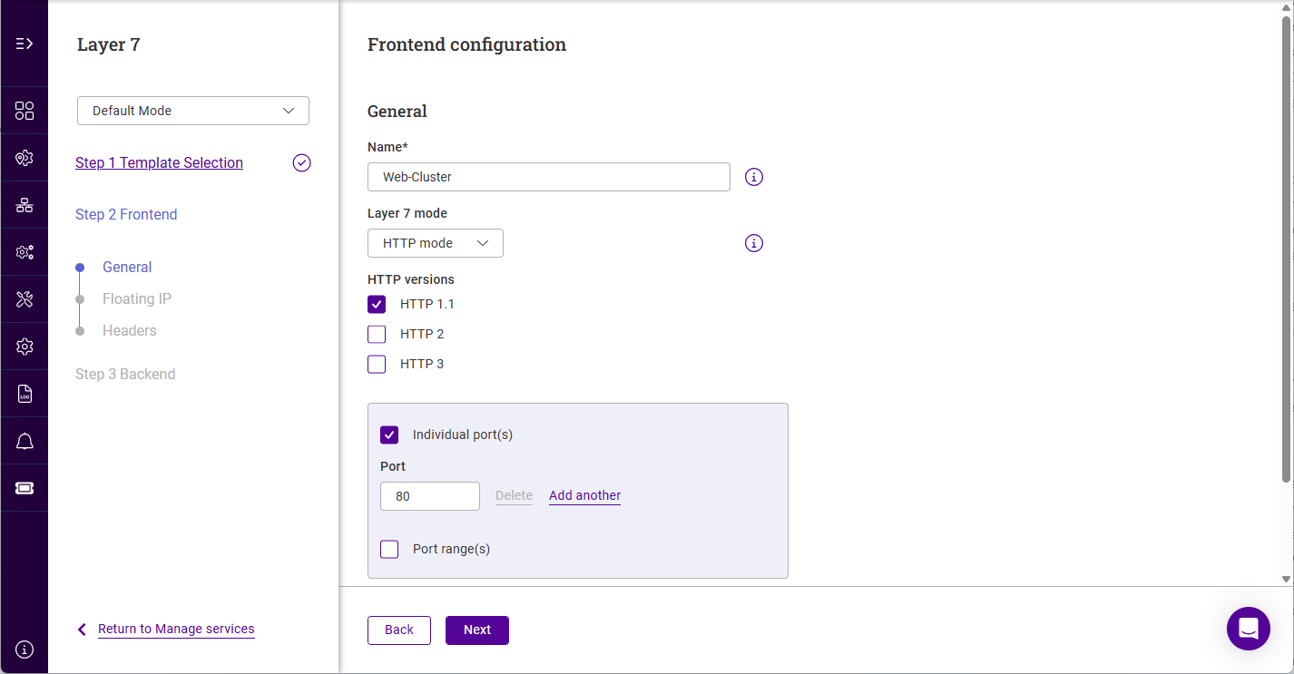
To display all settings, change Default Mode to Advanced Mode.
-
Specify a suitable name for the service, e.g. Web-Cluster.
-
Select the required Layer 7 mode, the options are:
Layer 7 mode Description HTTP mode
Use this mode if the Virtual Service will handle only HTTP traffic. This allows more flexibility in the processing of connections. When using persistence types such as HTTP Cookie and HTTP Application, HTTP mode must be selected. In addition, the HAProxy log will show more information on the client requests and Real Server responses.
TCP mode
Use this mode to support all non HTTP traffic such as HTTPS, RPC, RDP, FTP, SIP etc.
-
For HTTP mode Services, select the required HTTP Version.
-
Specify the required port(s) using the Individual port(s) and Port range(s) options.
-
If required, scroll down to display the remaining options.
-
If SSL termination is required, enable (check) the Enable SSL termination checkbox.
-
Specify the required HTTPS port(s) using the Individual port(s) and Port range(s) options.
For more information on SSL termination, see SSL/TLS Termination.
-
-
If required, enable (check) TCP keep alive. This enables the transmission of TCP keep-alive on both the client and the server sides of the connection.
-
If required, enable (check) Proxy protocol. This will configure the layer 7 VIP to expect Proxy Protocol Headers for all connections.
-
Click Next.
-
Specify the required Floating IP that the service should be associated with.
-
If the required address already exists, select the address.
-
If the required address does not exist, click Add floating IP.
-
Select the IP Group (subnet) where the Floating IP should be brought up.
For details on configuring IP groups please refer to XXXX. -
Specify a suitable IP address for the service, e.g. 10.11.45.125.
-
Click Add.
-
-
-
Ensure that the required Floating IP is selected.
-
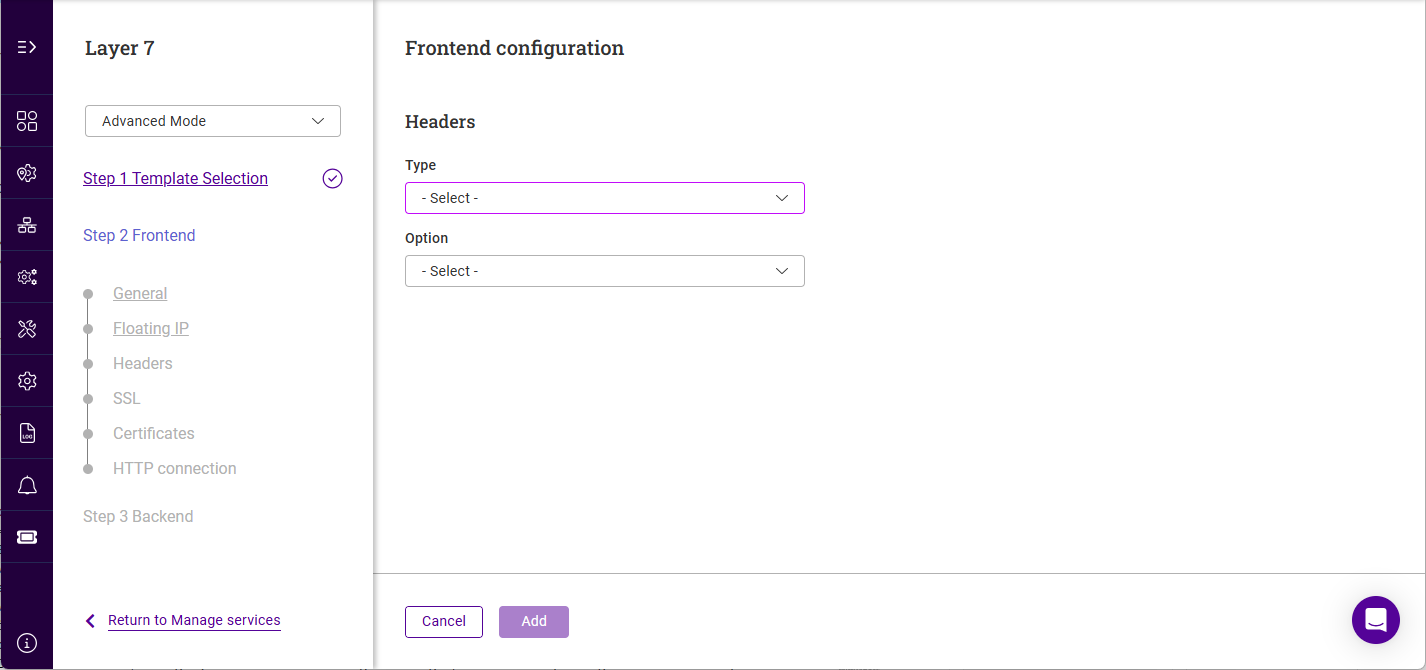
Click Next, the Frontend configuration - Headers screen will be displayed.
-
Click Add
-
Select the Header Type, the options are:
Type Description Request
Affect specified HTTP header fields in HTTP request messages
Response
Affect specified HTTP header fields in HTTP response messages.
-
Select the required Option, the options are:
Option Description Add
Append an HTTP header field. If a header field of the same name already exists then an additional header field will still be appended.
Set
Append an HTTP header field. If a header field of the same name already exists then it is first removed before a new one is appended. This is useful for handling security information which external users must not be able to set themselves.
Delete
Remove all HTTP header fields of a specified name.
Replace
Perform a regular expression powered "find and replace" operation on all HTTP header field values of a specified name.
-
Specify the required Name.
-
Specify the required Value.
-
Click Add.
-
Repeat to add additional Headers.
For more information on Headers, see HTTP Headers. -
Click Next, the Frontend Configration - SSL screen will be displayed (if SSL was enabled).
-
Specify the required Forwarding Mode, the options are:
Forwarding mode Description Source Network Address Translation (SNAT)
The mode requires no Real Server changes but is not as fast as DR mode. Also it’s non transparent and therefore looses the client source IP information.
Direct Routing
Requires the "ARP Problem" to be solved on each Real Server. For more information on DR mode, see Layer 4 DR Mode.
Destination Network Address Translation (DNAT)
Requires each Real Server to have its default gateway set as the load balancer.
Tunneling
Similar to DR mode but works across IP encapsulated tunnels
For full details of all modes, see XXXX. -
Click Next.
-
Specify the required Health check type and the associated settings, the options are:
Settings with (Adv) specified are only displayed in advanced mode. Health Check Type Description Settings Connect to port
Attempt to make a connection to the specified port
Check port (Adv) : the port to monitor. If specified this setting overrides the default which is the Real Server port. For multiport VIPs where the Real Server port field is left blank, the default check port is the first in the list. This can be changed using this field if required.
External script
Use a custom file for the health check
Check port (Adv) : See above.
External check script : Specify the script to use.For details on adding new health check scripts, see [XXXX]. Negotiate DNS
Perform a DNS check
Request to send : The file/page to open. This can also be the name of a server-side script that’s used to check the health of the backend application.
Response expected : The content expected in the specified file/page. The Response Expected can also be any valid regular expression statement. The result can be inverted by selecting "Not EqualsNegotiate FTP
Perform an FTP check
Check port (Adv) : See above
Username : Specify a username if authentication is required
Password : Specify a password if authentication is required
Request to send : See above
Response expected : See aboveNegotiate HTTP
Perform an HTTP check
Check port (Adv) : See above
Host Header : If the Real Server is configured to require a Host header, specify the value here
Request to send : See above
Response expected : See aboveNegotiate HTTP (Proxy)
Perform a Proxy check
Check port (Adv) : See above
Request to send : See above
Response expected : See aboveNegotiate HTTPS
Perform an HTTPS check
Check port (Adv) : See above
Request to send : See above
Response expected : See aboveNegotiate IMAP
Perform an IMAP check
Check port (Adv) : See above
Username : See above
Password : See aboveNegotiate IMAPS
Perform an IMAPS check
Check port (Adv) : See above
Username : See above
Password : See aboveNegotiate LDAP
Perform an LDAP check
Check port (Adv) : See above
Username : See above
Password : See aboveNegotiate MySQL
Perform an MySQL check
Check port (Adv) : See above
Database name : Specify the name of the MySQL database
Username : See above
Password : See above
Request to send : See aboveNegotiate NNTP
Perform an NNTP check
Check port (Adv) : See above
Negotiate POP
Perform a POP check
Check port (Adv) : See above
Username : As above
Password : As aboveNegotiate POPS
Perform a POPS check
Check port (Adv) : See above
Username : As above
Password : As aboveNegotiate RADIUS
Perform a RADIUS check
Check port (Adv) : See above
Radius Secret : Specify the Radius secret string
Username : As above
Password : As aboveNegotiate SMTP
Perform an SMTP check
Check port (Adv) : See above
No checks, always off
All Real Servers are marked offline
No health checks, all Real Servers are assumed to be down
No checks, always on
All Real Servers are marked online
No health checks, all Real Servers are assumed to be up
Ping Server
Use a simple ICMP ping to perform health checks
Sends an ICMP echo request packet to the Real Server
-
Click Next.
-
If required, specify the Fallback server.
-
If the fallback server already exists, select the server.
-
If the fallback server does not exist, click Add fallback server.
-
Specify a suitable Name.
-
Specify a Certificate if required.
-
Specify the Type.
-
If Internal is selected, specify the Page contents.
-
If External is selected, specify the IP address and Port of the fallback server.
-
-
-
Click Add.
-
-
Ensure the correct Fallback server is selected.
-
Select the required Forwarding Method for the fallback server.
-
Click Next.
-
Use the Enable Persistence checkbox to enable/disable persistence. Persistent connections are required for some protocols such as FTP and SIP. It’s beneficial when using SSL to avoid re-negotiation and can be required with HTTP if your web application cannot keep state between Real Servers.
-
If enabled, set the required Timout. The timeout is reset on every new client connection.
-
If enabled, set the Granularity. The granularity level sets how many clients are grouped to a single Real Server. The default mask is 255.255.255.255 (or 128 for IPv6), meaning persistence is per individual client host, but less specific masks like 255.255.255.0 (or /24 for IPv6) can be used to direct all clients within a network to the same real server.
-
Click Next.
-
If required, configure the Feedback Method.
-
Select Agent to use utilise runtime data from the feedback agent installed on each Real Server.
-
Specify the Feedback Agent Port, the default in 3333.
-
-
Select HTTP to use any HTTP server responding on port 3333 to give feedback information to the load balancer.
-
-
Click Next.
-
Click Add real server.
-
Specify a suitable Name, e.g. WEB1.
-
Specify the Real Server’s IP Address.
-
Specify the Real Server’s Port.
-
Specify the Real Server’s weight. This is an integer specifying the capacity of a server relative to the others in the pool, valid values are 0 to 65535, the default is 100. The higher the value, the more connections the server will receive. If the weight is set to 0, the server will effectively be placed in drain mode.
-
Specify the Real Server’s Minimum Connections. This is an integer specifying the lower connection threshold of a server. The valid values are 0 through to 65535. The default is 0, which means the lower connection threshold is not set. If set, the server will receive new connections when the number of its connections drops below its lower connection threshold. If not set but Maximum Connections is set, the server will receive new connections when the number of its connections drops below 3/4 of its upper connection threshold.
-
Specify the Real Server’s Maximum Connections. This is an integer specifying the upper connection threshold of a server. The valid values of Maximum Connections are 0 through to 65535. The default is 0, which means the upper connection threshold is not set.
-
Click Add.
-
Repeat these steps to add additional Real Servers.
-
Once all Real Servers have been added, click Submit to create the service.
Duplicating Layer 7 Services
If you have existing Layer 7 Services, these can be duplicated. During the duplication process, the name and the IP address and/or port must be changed so that it does not clash with the source Service.
To duplicate an existing layer 7 Service:
-
Click the three dots menu next to the Service you’d like to duplicate.
-
Click Duplicate.
-
Update the Name for the new Service.
-
Update the Port if required.
-
Click Next.
-
Update the Floating IP address if required.
At least one of these settings must be changed. -
Click Update.
GSLB Services
GSLB enables traffic to be load balanced across multiple geographically dispersed servers. When used in conjunction with the failover and high availability features of the appliance, GSLB enables highly available, multi-site load balanced environments to be created. GSLB functionality is provided using the Open Source Polaris GSLB.
Key Concepts
GSLB enables the load balancer(s) to provide intelligent DNS responses to inbound client queries for one or more sub domains. The responses given depend on the health of each endpoint and if Topology is configured, the location of those endpoints relative to the client making the request. Where GSLB is deployed along side application load balancing, the endpoints are usually the VIPs that are configured at each site. Where application load balancing is not used and only GSLB is configured, the endpoints are normally the Real Servers.
DNS delegation is used to delegate responsibility for the sub domain(s) to the GSLB service on the load balancers. Once delegated, it is the GSLB service on the load balancers that is responsible for providing the response to DNS queries for that sub domain.
In a two site setup with an HA pair of load balancers in each site, once GSLB and DNS delegation are correctly configured, the four load balancers act as intelligent name servers for the sub domains specified.
Key features
-
Reliable health checking service supporting both TCP, HTTP(S) and custom external checks so that only healthy members/endpoints are returned on lookups
-
Failover, round robin and also a topology method that directs clients to servers in the same location
-
Can return single or multiple (up to 1024) answers at once
-
Option to fallback to any healthy server or refuse the query
-
Uses EDNS Client Subnet (ECS) by default so the client IP address / subnet is used when considering topology. For more details, see [GSLB Advanced Configuration].
| For additional information, see our GSLB blog. |
GSLB Configuration
GSLB is configured using the WebUI menu option: Cluster Configuration > GSLB Configuration. Four tabs are used to configure GSLB as illustrated below:
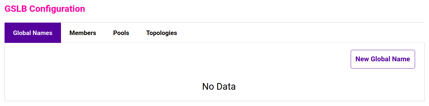
Global Names - Define the sub domain(s) that GSLB responds to.
Members - Are returned to clients in DNS responses, also known as "endpoints".
Pools - Associate one or more Global Names with the relevant Members. Also defines health checks, load balancing method, timeouts and various other settings.
Topologies - Define how network subnets and host addresses map to sites. In a multi-site deployment, this can be used to ensure that clients connect to the nearest / most appropriate site. A topology groups together the member(s) for a particular site and the clients who would normally connect via those members. Members and clients can be specified using a subnet address such as 10.0.0.0/24 or a host address such as 10.0.0.1/32.
The following table details the options in each tab.
| Tab | Setting | Description | ||||
|---|---|---|---|---|---|---|
Global Names |
Name |
Name can be a combination of "0-9", "a-z", "A-Z", "-" (dash), "_" (underscore) or a "." (dot). |
||||
Hostname |
A valid RFC 1123 hostname, for example www.example.com. |
|||||
TTL |
TTL is how long to cache the (hostname) DNS response in seconds. For example 3600 would be equal to 1 hour, the minimum (and default) value is "0" (0s). |
|||||
Members |
Name |
Name can be a combination of "0-9", "a-z", "A-Z", "-" (dash), "_" (underscore) or a "." (dot). |
||||
IP |
A valid IPv4 address, for example 10.0.1.1. |
|||||
Monitor IP |
A valid IPv4 address, for example 10.0.1.1. |
|||||
Weight |
Weight of the server, min: 0 (server is disabled), max: 10. |
|||||
Pools |
Name |
Name can be a combination of "0-9", "a-z", "A-Z", "-" (dash), "_" (underscore) or a "." (dot). |
||||
Monitor |
The type of health check to use. The options are: |
|||||
Monitor - HTTP |
Perform a HTTP or HTTPS GET depending on Monitor Use SSL. Succeeds if HTTP response status is 200 or one of the codes specified in Monitor Expected codes.
|
|||||
Monitor - TCP |
Perform a TCP connect. Optionally: send text, read response and match a regex pattern.
|
|||||
Monitor - Forced |
Forces a member to be either UP or DOWN effectively disabling health checking.
|
|||||
Monitor - External |
Will run the script selected in the Monitor Script dropdown. The check will receive the IP address and port of the member and any additional arguments that are passed. If a Monitor Result is set, the check will be deemed a success if the script returns the configured string. If there is no Monitor Result the exit code will be used.
|
|||||
Monitor - External Dynamic Weight |
This will dynamically adjust the weight based on the output of the health check script. It should output between 0 and 10, 10 being of the highest priority and 0 being offline and removed from the pool. The exit code should be 0 at all times, anything else will report as a health check failure.
|
|||||
LB Method |
The load balancing method to use. The options are:
|
|||||
Global Names |
A Pool can be associated with one or more global names. A pool requires at least one global name. Use the CTRL key to select multiple global names. |
|||||
Members |
A pool must have at least one endpoint member. Drag and drop the endpoints from Available Members to _Members in Use.
|
|||||
Advanced > |
In seconds, min: 1, max: 3600. |
|||||
Advanced > |
In milliseconds, min: 100 (0.1s), max: 10000 (10 seconds). |
|||||
Advanced > |
Retry min: 0, max: 5, default is "0" no retries. |
|||||
Advanced > |
Resolution behavior when all members of the pool are DOWN. The options are:
|
|||||
Advanced > |
Maximum number of A records to return in response, large responses will go over TCP min: "1", max: "1024", default: "1". |
|||||
Toplogies |
Name |
Name can be a combination of "0-9", "a-z", "A-Z", "-" (dash), "_" (underscore) or a "." (dot). |
||||
IP/CIDR |
A comma separated list of valid IPv4 address or CIDR denoted IP blocks for example "10.1.1.0/24, 10.1.1.2". |
GSLB Service IP Address & Port
By default, the GSLB service listens on TCP & UDP port 53 on all appliance IP addreses. This can be changed if required. For more details, see [Service Socket Addresses].
External Health Check Scripts (GSLB)
Custom GSLB health checks can be created and modified using the WebUI.
Adding Health Check Scripts
New scripts can be created either by using the script templates or by uploading files from an external source.
Once the health check has been added, it will appear in the Health Check Scripts list and in the Monitor Script dropdown as explained in Using Script Templates above.
SSL/TLS Termination
Concepts
SSL/TLS termination can be handled in the following ways:
-
On the Real Servers (recommended) - aka SSL Passthrough
-
On the load balancer - aka SSL Offloading
-
On the load balancer with re-encryption to the backend servers - aka SSL Bridging
The following sections describe each method.
On the Real Servers (SSL Passthrough)
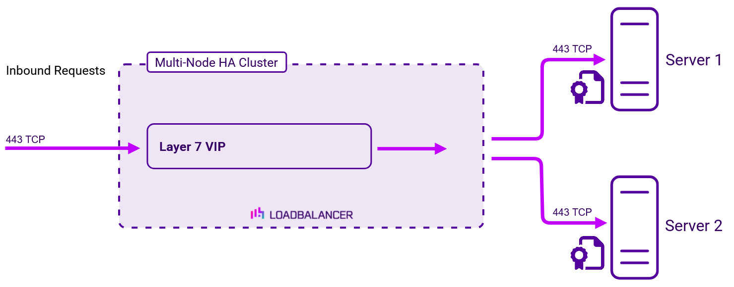
In this case, SSL certificates are installed on each Real Server in the normal way. Data is encrypted from client to server which provides full end-to-end data encryption.
The load balancer is configured with a layer 7 service that listens on port 443 and distributes inbound requests to the Real Servers on port 443 as shown below:
-
This is our recommended solution. Terminating SSL on the load balancer can be very CPU intensive and in most cases, for a scalable solution, terminating SSL on the Real Servers is the best option.
-
It’s not possible to use HTTP cookie persistence, header manipulation and other layer 7 techniques that control how traffic is sent to the Real Servers because all data is encrypted as it passes through the load balancer.
On the load balancer (SSL Offloading)
| Terminating SSL on the load balancer can be very CPU intensive. In most cases, for a scalable solution, terminating SSL on the Real Servers (SSL Passthrough) is the best option. |
| For more information on configuring SSL termination on the load balancer see Adding Layer 7 Virtual Services. |
Here, the SSL certificate is installed on the load balancer. Data is encrypted from the client to the load balancer. Data from the load balancer to the backend servers is un-encrypted.
The load balancer is configured with a layer 7 service that handles both decryption and load balancing as shown below.

-
By default, a self-signed certificate is used for new Services. Certificates can be created or uploaded as explained in [Certificates].
-
Cookie based persistence and other layer 7 techniques can be used to control traffic flow to the Real Servers.
On the load balancer with re-encryption to the backend servers (SSL Bridging)
| Terminating SSL on the load balancer can be very CPU intensive. In most cases, for a scalable solution, terminating SSL on the Real Servers (SSL Passthrough) is the best option. |
| For more information on configuring SSL termination on the load balancer see Adding Layer 7 Virtual Services. |
Here, the SSL certificate is installed on the load balancer and the Real Servers. Data is encrypted from the client to the load balancer and from the load balancer to the backend servers.
The load balancer is configured with a layer 7 service that handles decryption, load balancing and re-encryption to the backend servers as shown below.
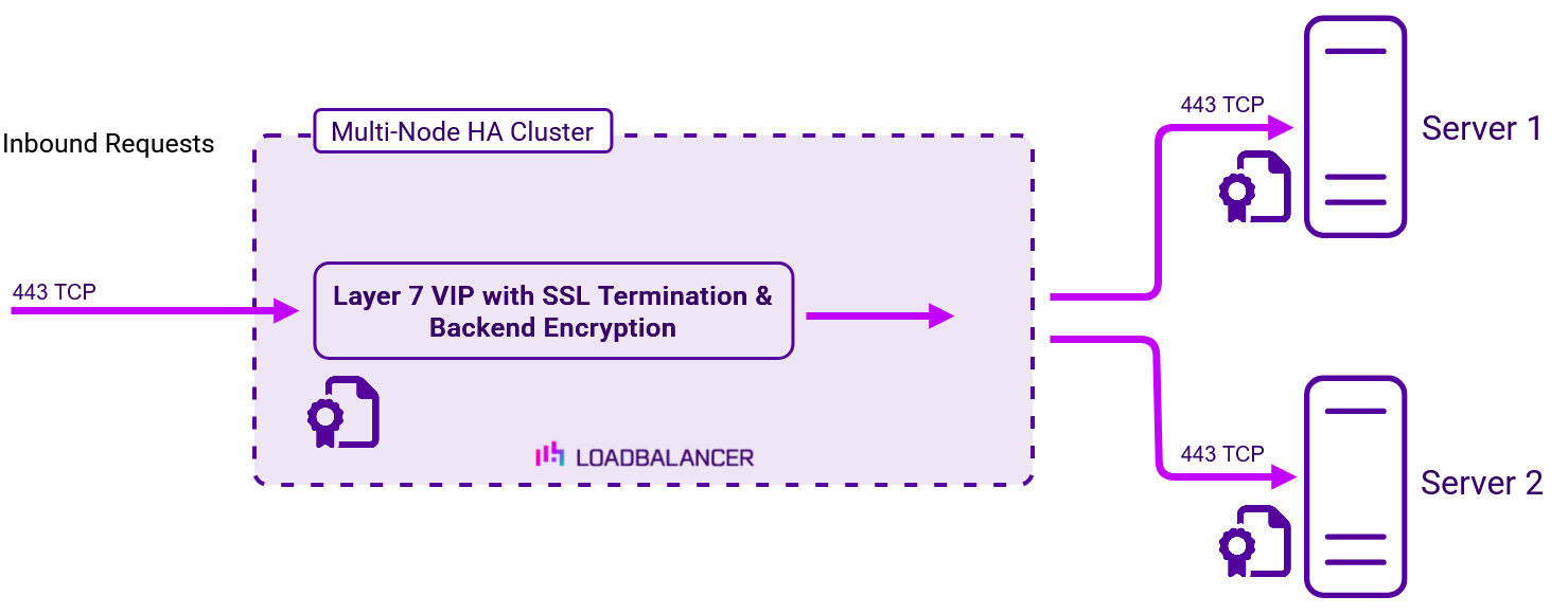
-
By default, a self-signed certificate is used for new Services. Certificates can be created or uploaded as explained in [Certificates].
-
Cookie based persistence and other layer 7 techniques can be used to control traffic flow to the Real Servers.
HTTP to HTTPS Redirection
HTTP to HTTPS redirection is supported both when terminating SSL on the Real Servers and when offloading SSL on the load balancer as described in the following sections.
When Terminating SSL on the Real Servers
This method requires two VIPs:
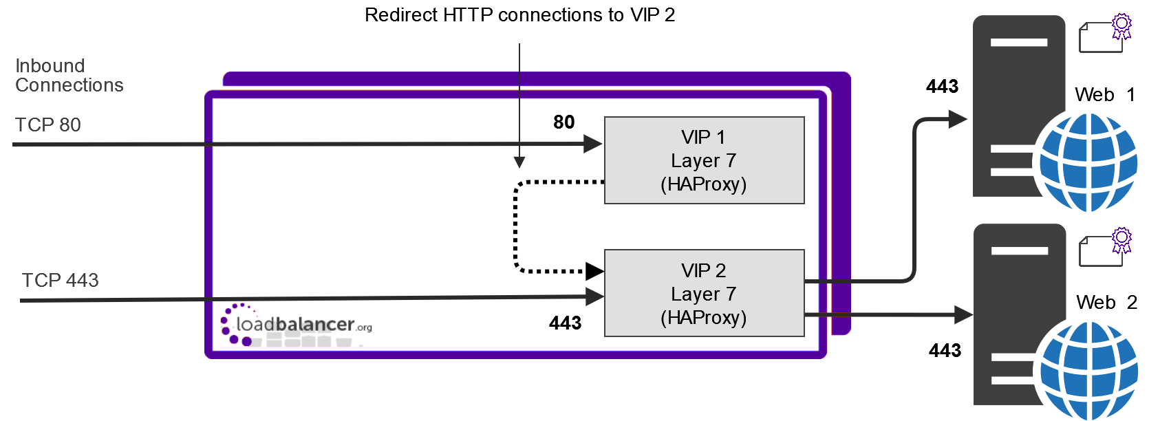
-
VIP 1 - This is a layer 7 HTTP mode VIP that listens on port 80 and redirects all requests to VIP 2.
-
This VIP does not require any Real Servers. Once configured, it will be shown purple/green in the System Overview.
-
Force to HTTPS is enabled - this is set by modifying the VIP, scrolling to the Other section and enabling Force to HTTPS.
Force to HTTPS is only available when the VIP is in HTTP mode.
-
-
VIP 2 - This is a layer 7 TCP mode VIP that listens on port 443 and load balances connections between Web 1 & Web 2.
-
This VIP is configured on the same IP address as VIP 1.
-
When Terminating SSL on the Load Balancer
This method requires one VIP:
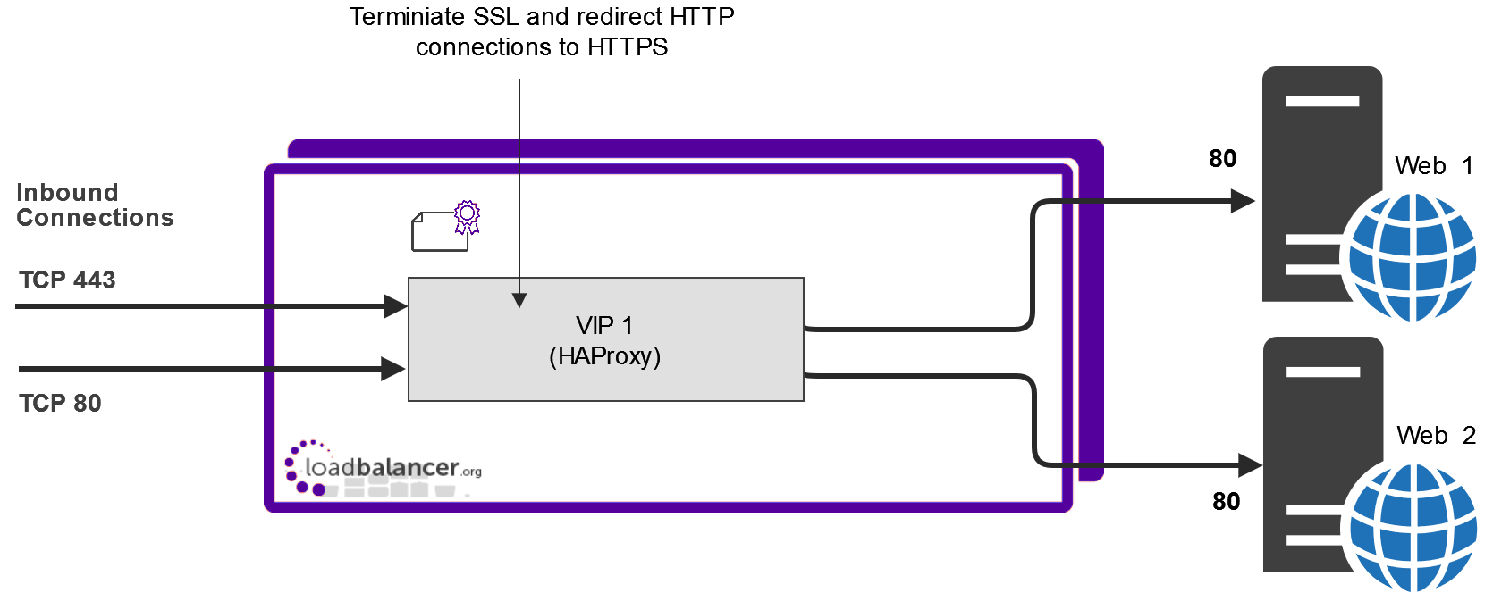
-
VIP 1 - This is a Layer 7 SNAT mode VIP configured in HTTP mode. It listens on port 80 and load balances the decrypted HTTP requests to Web 1 & Web 2.
-
This VIP also handles SSL termination. To configure SSL termination at the same time as creating the layer 7 VIP, click [Advanced] and in the termination section enable (check) the Create HAProxy SSL Termination option.
-
Force to HTTPS is enabled - this is set by modifying the VIP, scrolling to the Other section and enabling Force to HTTPS.
Force to HTTPS is only available when the VIP is in HTTP mode. If you want to re-encrypt the data from the load balancer to the Real Server, enable the Re-encrypt to Backend option for the each Real Server. For more information on using this option, see SSL Termination on the Load Balancer with Re-encryption (SSL Bridging).
-
Unresolved include directive in modules/admin/pages/cluster-configuration.adoc - include::partial$transparency-at-layer7.adoc[]
HTTP Headers
For HTTP Mode Virtual Services, HTTP header fields can be added, set, deleted, and replaced.
| For more information on configuring HTTP Headers see Adding Layer 7 Virtual Services. |
The following examples illustrate how header rules can be used.
Example 1
A secure deployment requires that the X-Forwarded-For header field in client requests never be trusted. The header is under the control of the client and could potentially contain misinformation set by a malicious client. All header fields of this name should be deleted from incoming requests.
Create the following header rule:
| Type | Option | Name | Value |
|---|---|---|---|
Request |
Delete |
X-Forwarded-For |
- |
Example 2
A poorly designed web service behind the load balancer leaks sensitive information through an HTTP response header field. The vulnerable response field looks like so: Database-Engine: MongoDB_3.4.14. All header fields of this name should be deleted from outgoing responses.
Create the following header rule:
| Type | Option | Name | Value |
|---|---|---|---|
Request |
Delete |
Database-Engine |
- |
Example 3
A web service behind the load balancer expects to receive information about client requests via HTTP header fields. The service expects to receive the source IP address, destination IP address, and destination port of the client’s initial connection to the load balancer, which it expects to find in header fields named X-Client-Source, X-Client-Dest, and X-Client-Dest-Port, respectively. The load balancer should add these header fields to incoming requests and populate their values appropriately. The load balancer should also delete any pre-existing header fields that use the field names that the web service is logging, to prevent clients from tampering with or injecting arbitrary data into the web service’s logs.
Create the following header rules:
| Type | Option | Name | Value |
|---|---|---|---|
Request |
Set |
X-Client-Source |
%ci |
Request |
Set |
X-Client-Dest |
%fi |
Request |
Set |
X-Client-Dest-Port |
%fp |
ACL rules
By default, an ACL is always created when a Virtual service is created. This links the frontend to the backend.
ACLs can also be created to control and direct traffic based on a set of defined rules. This functionality is also known as URL rewriting, URL redirection, URL forwarding or content switching.
Different types of ACLs can be created. Some ACLs are dependent on information from the application layer and so are only available for HTTP mode virtual services. The ACL types and their supported modes are listed below.
| ACL Type | TCP Mode Support | HTTP Mode Support |
|---|---|---|
IP Address |
|
|
Port |
|
|
Path |
|
|
Path begins |
|
|
Path substring |
|
|
Path ends |
|
|
HDR |
|
|
HDR host |
|
|
HDR begins (Host) |
|
|
Query |
|
|
Flags |
|
|


Network/Transport Layer-Based ACLs
IP Address (aka src):
-
Match against the source IP address of the request.
-
Bool:
-
Equals: Perform action if URL/Text value matches.
-
Not equal: Perform action if URL/Text value does not match.
-
-
URL/Text: IP address to compare the request’s source IP address to. CIDR notation can be used and multiple comma-separated values can be given, e.g.
10.0.0.0/8 123.45.67.8. -
Action: Action to perform if condition is met. See ACL Actions.
Port (aka dst_port):
-
Match against the destination TCP port of the request.
-
Bool:
-
Equals: Perform action if URL/Text value matches.
-
Not equal: Perform action if URL/Text value does not match.
-
-
URL/Text: Integer to compare the request’s destination TCP port to.
-
Action: Action to perform if condition is met. See ACL Actions.
URL-Based ACLs
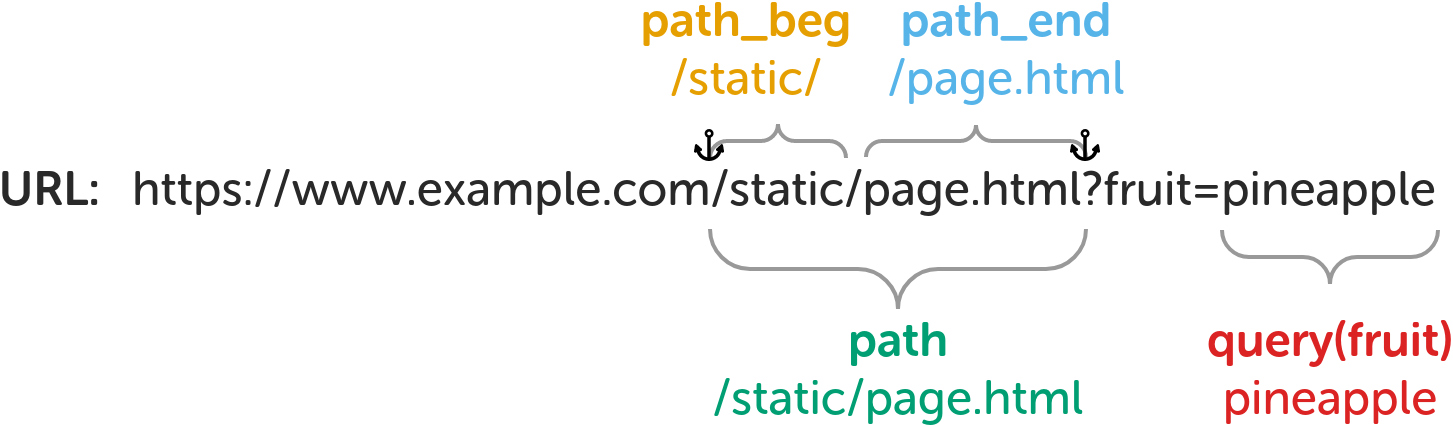
path:
-
Match against the request’s full URL path, which starts at the first slash and ends before the (optional) question mark (signifying the start of the query string).
-
Bool:
-
Equals: Perform action if URL/Text value matches.
-
Not equal: Perform action if URL/Text value does not match.
-
-
URL/Text: String to compare the full URL path to, e.g.
static/page.html. -
Action: Action to perform if condition is met. See ACL Actions.
path_beg:
-
Match against the beginning of the request’s URL path.
-
Bool:
-
Equals: Perform action if URL/Text value matches.
-
Not equal: Perform action if URL/Text value does not match.
-
-
URL/Text: String to compare the beginning of the URL path to, e.g.
/static/or/level_1/level_2/. -
Action: Action to perform if condition is met. See ACL Actions.
path_beg:
-
TBC
-
Match against the end of the request’s URL path.
-
Bool:
-
Equals: Perform action if URL/Text value matches.
-
Not equal: Perform action if URL/Text value does not match.
-
-
URL/Text: String to compare the end of the URL path to, e.g.
/page.htmlor.png. -
Action: Action to perform if condition is met. See ACL Actions.
Header-Based ACLs
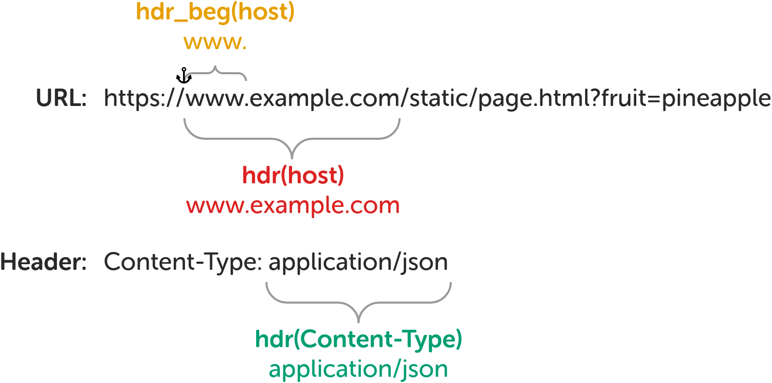
hdr_host (aka hdr(host)):
-
Match against the request’s full Host header.
-
Bool:
-
Equals: Perform action if URL/Text value matches.
-
Not equal: Perform action if URL/Text value does not match.
-
-
URL/Text: String to compare the full Host header to, e.g.
www.example.comoren.wikipedia.org. -
Action: Action to perform if condition is met. See ACL Actions.
hdr_beg(host):
-
Match against the beginning of the request’s Host header.
-
Bool:
-
Equals: Perform action if URL/Text value matches.
-
Not equal: Perform action if URL/Text value does not match.
-
-
URL/Text: String to compare the beginning of the Host header to, e.g.
www.oren.. -
Action: Action to perform if condition is met. See ACL Actions.
hdr:
-
Match against a specified request header.
-
Header/Param: Name of the request header to match against, e.g.
Content-Type. -
Bool:
-
Equals: Perform action if URL/Text value matches.
-
Not equal: Perform action if URL/Text value does not match.
-
-
URL/Text: String to compare the specified request header to, e.g.
application/json. -
Action: Action to perform if condition is met. See ACL Actions.
Miscellaneous ACLs
Detected SNI:
-
Match against the SNI detected in a non terminated SSL connection.
-
Bool:
-
Equals: Perform action if URL/Text value matches.
-
Not equal: Perform action if URL/Text value does not match.
-
-
URL/Text: String to compare the SNI field to, e.g.
www.example.com. -
Action: Action to perform if condition is met. See ACL Actions.
Reported SNI:
-
Match against the SNI in an HAProxy terminated SSL connection.
-
Bool:
-
Equals: Perform action if URL/Text value matches.
-
Not equal: Perform action if URL/Text value does not match.
-
-
URL/Text: String to compare the SNI field to, e.g.
www.example.com. -
Action: Action to perform if condition is met. See ACL Actions.
Flags:
-
Match based on the status of flags set by other ACL rules.
-
Bool:
-
Equals: Perform action if condition described by URL/Text field evaluates to true.
-
Not equal: Perform action if condition described by URL/Text field does not evaluate to true.
-
-
URL/Text: Condition to test, e.g.
flag_a || flag_borprotected_path internal_src_addr. -
Action: Action to perform if condition is met. See ACL Actions.
| See ACL Examples for an example of how to use the flags feature. |
Free Type:
-
Free-form custom ACL rule(s) to write into the HAProxy configuration verbatim.
-
Freetype: ACL configuration line(s) to write into the HAProxy configuration file.
| Multiple ACLs can be defined in a single block. Enter one ACL per line. |
| Full and detailed documentation on how to write ACLs can be found in the HAProxy Configuration Manual, here. |
ACL Actions
When an ACL rule matches an action is taken (or, alternatively, an action is taken when the rule doesn’t match, depending on the "bool" setting of the rule). Some actions are dependent on information from the application layer and so are only available for HTTP mode virtual services. The different actions and their supported modes are listed below.
ACL Type |
TCP Mode Support |
HTTP Mode Support |
Drop |
|
|
Deny |
|
|
Set Flag |
|
|
URL Location |
|
|
URL Prefix |
|
|
Use Backend |
|
|
Use Server |
|
|
-
Drop (aka reject): Stop and immediately close the connection without sending a response.
-
Deny: Stop and immediately deny the request, emitting the chosen HTTP status code as a response.
-
Status code: Status code to use as a response.
-
200 OK
-
400 Bad Request
-
403 Forbidden
-
405 Method Not Allowed
-
408 Request Timeout
-
425 Too Early
-
429 Too Many Requests
-
500 Internal Server Error
-
502 Bad Gateway
-
503 Service Unavailable
-
504 Gateway Timeout
-
-
-
Set Flag: Set a flag for use in subsequent ACL rules of type "Flag".
-
Location/Value: Name of the flag to set, e.g.
flag_aorprotected_path.
-
-
URL Location (aka redirect location): Redirect the request to the exact location specified, using a 301 Moved Permanently status code.
-
Location/Value: Exact location to redirect to, e.g.
https://en.wikipedia.org/wiki/User_Datagram_Protocol.
-
-
URL Prefix (aka redirect prefix): Redirect the request to the URL path originally requested prefixed with a specified string, using a 301 Moved Permanently status code.
-
Location/Value: String to prefix to the requested URL path to create the redirect location, e.g.
https://www.example.com.
-
-
Use Backend: Use the specified backend, or another virtual service, to handle the request.
-
Location/Value: Name of a valid backend, or another virtual service, to use, e.g.
apache_srv_cluster_b.
-
-
Use Server: Use the specified server to handle the request.
-
Location/Value: Name of a valid real server, in the same virtual service or backend, to use, e.g.
apache_srv_7.
-
ACL Examples
Example 1
A virtual service occasionally sees requests for a retired domain, www.foo.com. These requests need to be redirected to the new domain: www.bar.com. For example, a request for https://www.foo.com/static/diagram.svg must be redirected to https://www.bar.com/static/diagram.svg.
ACL type to use: hdr_host, matching against www.foo.com.
ACL action to use: URL Prefix, with the prefix https://www.bar.com.
Example 2
A web service has been moved: previously, all of its resources were located under /web-service/, but now everything is located under /legacy/web-service/. Any requests for old locations, whose paths start with just web-service, must be redirected to the correct new locations.
ACL type to use: path_beg, matching against /web-service/.
ACL action to use: URL Prefix, with the prefix /legacy.
Example 3
A web service hosts an administration panel which is located under /admin/. The only legitimate use of this panel should be from users on the local network, which is 10.0.0.0/8. Any non-local users attempting to access the administration panel should be redirected to a branded page, located at https://example.com/restricted.html, which explains that they have attempted to access a restricted part of the service.
First ACL type to use: path_beg, matching against /admin/.
First ACL action to use: Set Flag, setting the flag is_admin_panel.
Second ACL type to use: IP Address, matching against the network 10.0.0.0/8.
Second ACL action to use: Set Flag, setting the flag is_local_user.
Third ACL type to use: Flags, matching against is_admin_panel !is_local_user.
Third ACL action to use: URL Location, with the location https://example.com/restricted.html.
The two flag names together, is_admin_panel !is_local_user, create a logical AND (a logical OR could be achieved, instead, by explicitly placing || between the flag names). The exclamation mark negates the match on is_local_user. The resulting expression of the third ACL will match, and cause the redirection action to be carried out, when is_admin_panel is true and is_local_user is false.
| The ACL that evaluates the two flags must be placed after the two ACLs that set the flags. |
Example 4
It’s necessary to force the use of a particular real server in some scenarios. This must be achieved by setting a particular query string parameter to the name of the server. For example, http://192.168.0.10/?server_override=apache_srv_dev should trigger the override ACL condition and send the request to the special server.
ACL type to use: Query, looking for the server_override parameter and matching against apache_srv_dev.
ACL action to use: Use Server, with the server name apache_srv_dev.
Example 5
You have the following VIPs, both with source IP persistence enabled:
-
VIP1 that listens on 192.168.10.10:80 and forwards traffic to the Real Servers on port 8080
-
VIP2 that listens on 192.168.10.10:443 and forwards traffic to the same Real Servers on port 4443
You want all requests from a particular client to be handled by the same Real Server irrespective of which VIP receives the request. You can’t group port 80 and 443 into a single VIP because port translation is used. To achieve the same objective, both VIPs are configured to share the same persistence table.
Advanced configurations
Layer 4
This section allows you to configure various layer 4 global settings.
Check Interval - Layer 4 health check interval in seconds. If this setting is too low, you may experience unexpected Real Server downtime.
Check Timeout - Layer 4 health check timeout in seconds. If this setting is too low, you may induce unexpected Real Server downtime.
Negotiate Timeout - Layer 4 negotiate health check timeout in seconds. The negotiate checks may take longer to process as they involve more server side processing than a simple TCP socket connect check. If this setting is too low, you may induce unexpected Real Server downtime.
TCP FIN Timeout - The time to remember an TCP session for after seeing a FIN packet.
UDP Timeout - The time to remember a session for after seeing a UDP packet. The timeout is reset on every UDP packet received.
Failure Count - Layer 4 number of times a check has to fail before taking server offline. The time to detect a failure and take down a server will be (check interval + check timeout) x failure count.
Quiescent - When a Real Server fails a health check, do we kill all connections?
When Quiescent is set to yes, on a health check failure the Real Server is not removed from the load balancing table, but the weight is set to 0. Persistent connections will continue to be routed to the failed server, but no new connections will be accepted. When Quiescent is set to no, the server is completely removed from the load balancing table on a health check failure. Persistent connections will be broken and sent to a different Real Server.
| Quiescent only applies to health checks - it has no effect on taking Real Servers offline in System Overview. To manually force a Real Server to be removed from the table, set Quiescent to no and arrange for the server to fail its health check. This may be done, for example, by shutting down the daemon or service, changing the negotiate check value, or shutting down the server. |
Layer 7
This section allows you to configure the various layer 7 global settings.
Logging - Set the required logging level for layer 7 services. Logs are written to /var/log/haproxy.log.
Redispatch - Allows HAProxy to break persistence and redistribute to working servers should failure occur. Normally this setting should not require changing.
Connection Timeout - HAProxy connection timeout in milliseconds. This setting should normally not require changing.
Client Timeout - HAProxy client timeout in milliseconds. This setting should normally not require changing.
Real Server Timeout - HAProxy Real Server timeout in milliseconds. This setting should not require changing.
Maximum Connections - HAProxy maximum concurrent connections. This setting should not require changing, unless you are running a high volume site. See also Maximum Connections for a Virtual Service (HAProxy).
eMail Alert From - Set the "from address" for email alerts.
eMail Alert To - Set the "to address" for email alerts.
eMail Server Address - Set the email server address as either an IP address or FQDN.
eMail Server Port - Set the email server TCP port.
| For more information on configuring email alerts, see [Configuring Email Alerts for Virtual Services]. |
Statistics page
Request Buffer Length - Set the health check buffer length in bytes.
| Changing this value will effect the performance of HAProxy. Do not make changes unless you know exactly what you are doing. |
Lower values allow more sessions to coexist in the same amount of RAM, and higher values allow some applications with very large cookies to work. The default value is 16384 bytes. It is strongly recommended not to change this from the default value, as very low values will break some services such as statistics, and values larger than the default size will increase memory usage, possibly causing the system to run out of memory. Administrators should consider reducing the Maximum Connections parameter if the request buffer is increased.
Header Buffer Length - Set the header buffer length, in bytes The header buffer is a section of the request buffer, reserved for the addition and rewriting of request headers. The default value is 1024 bytes. Most applications will only require a small header buffer, as few headers are added or rewritten.
Persistence Table Replication - When enabled, HAProxy’s persistence tables are replicated to the Secondary device.
Replication Port - Set the TCP port to use for persistence table replication. The default port is TCP 7778.
Enable Multi-threading - This can improve performance if limits are being reached.
Default Number of Threads - Let the appliance choose a sensible number of worker threads. By default this will be be the same as the number of cores available when HAProxy starts or reloads.
| Multi-threading is enabled by default and the number of threads is auto set based on the number of detected CPUs / vCPUs. |