Topologies & Load Balancing Methods
Where the appliance sits in your network and the load balancing methods it supports.
One-Arm and Two-Arm Topologies
The number of "arms" is a descriptive term for how many interfaces are used to connect a device to a network. It’s common for a load balancer that uses a routing method (NAT) to have a two-arm configuration although one-arm is also supported. Proxy based load balancers commonly use a one-arm configuration although two-arm is also supported.
One-Arm
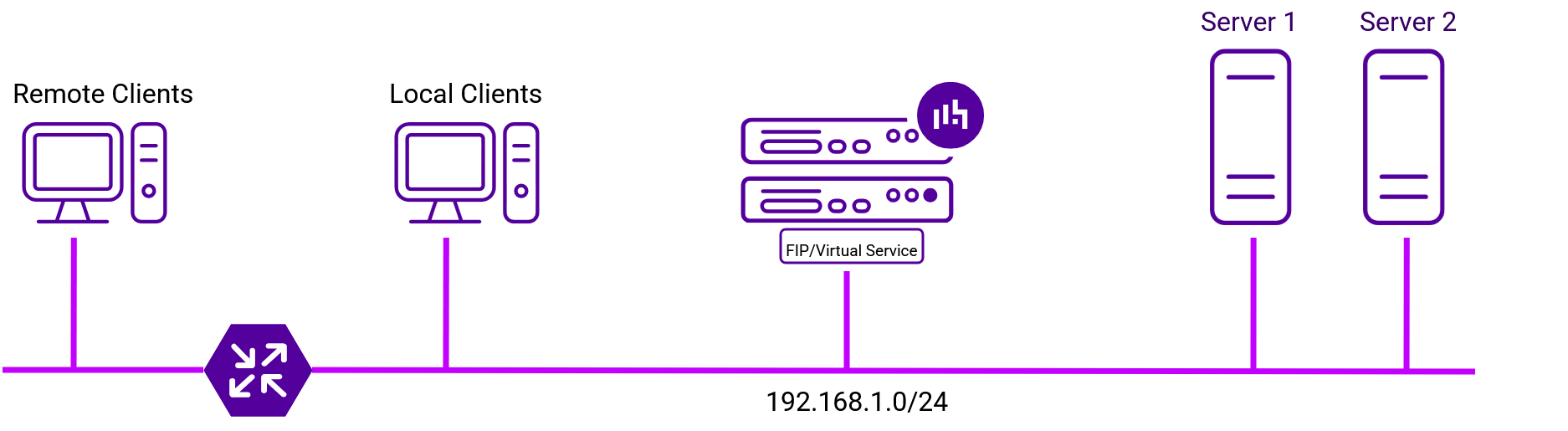
The FIP/Virtual Service and the load balanced servers are located in a single subnet. The load balancer requires a single network interface.
Two-Arm
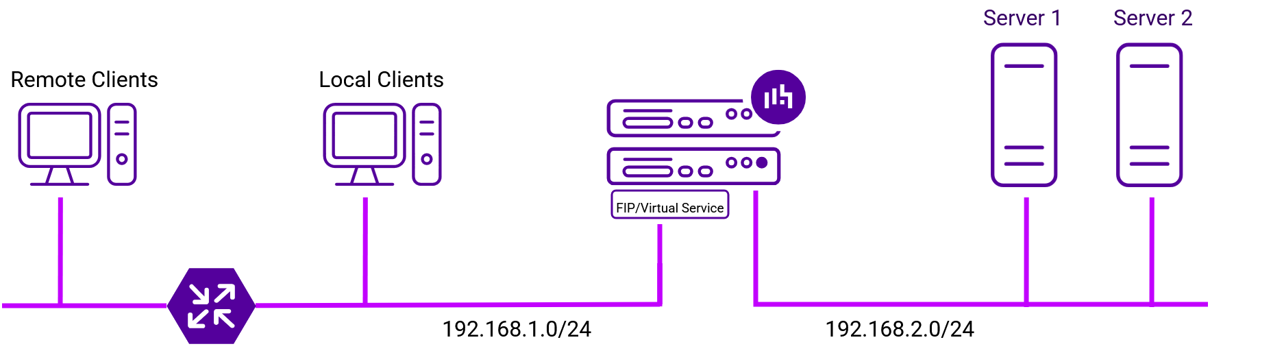
Here, 2 subnets are used. The FIP/Virtual Service is located in one subnet and the load balanced Real Servers are located in the other. The load balancer requires 2 interfaces, one in each subnet as shown in the diagram below.
| This can be achieved by using two network adapters, or by creating VLANs on a single adapter. |
Supported Load Balancing Methods
The Loadbalancer.org appliance supports multiple load balancing methods/modes. These can be used at the same time or in combination with each other and are described in the table below.
| Layer | Method/Mode | Comments | Topology | Note |
|---|---|---|---|---|
4 |
DR Mode |
Ultra-fast layer 4 load balancing
|
One-Arm (*) |
1 |
4 |
DNAT Mode |
Fast Layer 4 load balancing
|
One-Arm or Two-Arm |
1 |
4 |
TUN Mode |
Similar to DR mode but works across IP encapsulated tunnels
|
One-Arm |
2 |
4 |
SNAT Mode |
Fast layer 4 load balancing
|
One-Arm or Two-Arm |
3 |
7 |
SNAT Mode |
Not as fast as layer 4 methods, but offers greater flexibility, supports remote server load balancing and advanced functionality such as multiple persistence methods, header manipulation and URL rewriting
|
One-Arm or Two-Arm |
4 |
7 |
SSL/TLS Termination |
Typically required to enable cookie persistence, header manipulation and URL rewriting in HTTPS streams
|
One-Arm or Two-Arm |
5 |
(*) DR mode can also be used in a multi-homed configuration where Real Servers are located in different subnets. In this case, the load balancer must have an interface in each subnet to enable layer 2 connectivity which is required for DR mode to operate.
Notes
-
Recommended for high performance fully transparent and scalable solutions.
-
Only required for DR mode implementations across routed networks (rarely used).
-
Useful when you want to load balance both TCP and UDP, but you’re unable to use DR mode or NAT mode due to network topology or Real Server related reasons.
-
Used across multiple environments including object storage, healthcare and various Microsoft application such as Exchange, IIS and RDS.
-
SSL/TLS termination is processor intensive - where possible, for a scalable solution terminating on the Real Servers is recommended. :leveloffset: +1
Layer 4 DR Mode
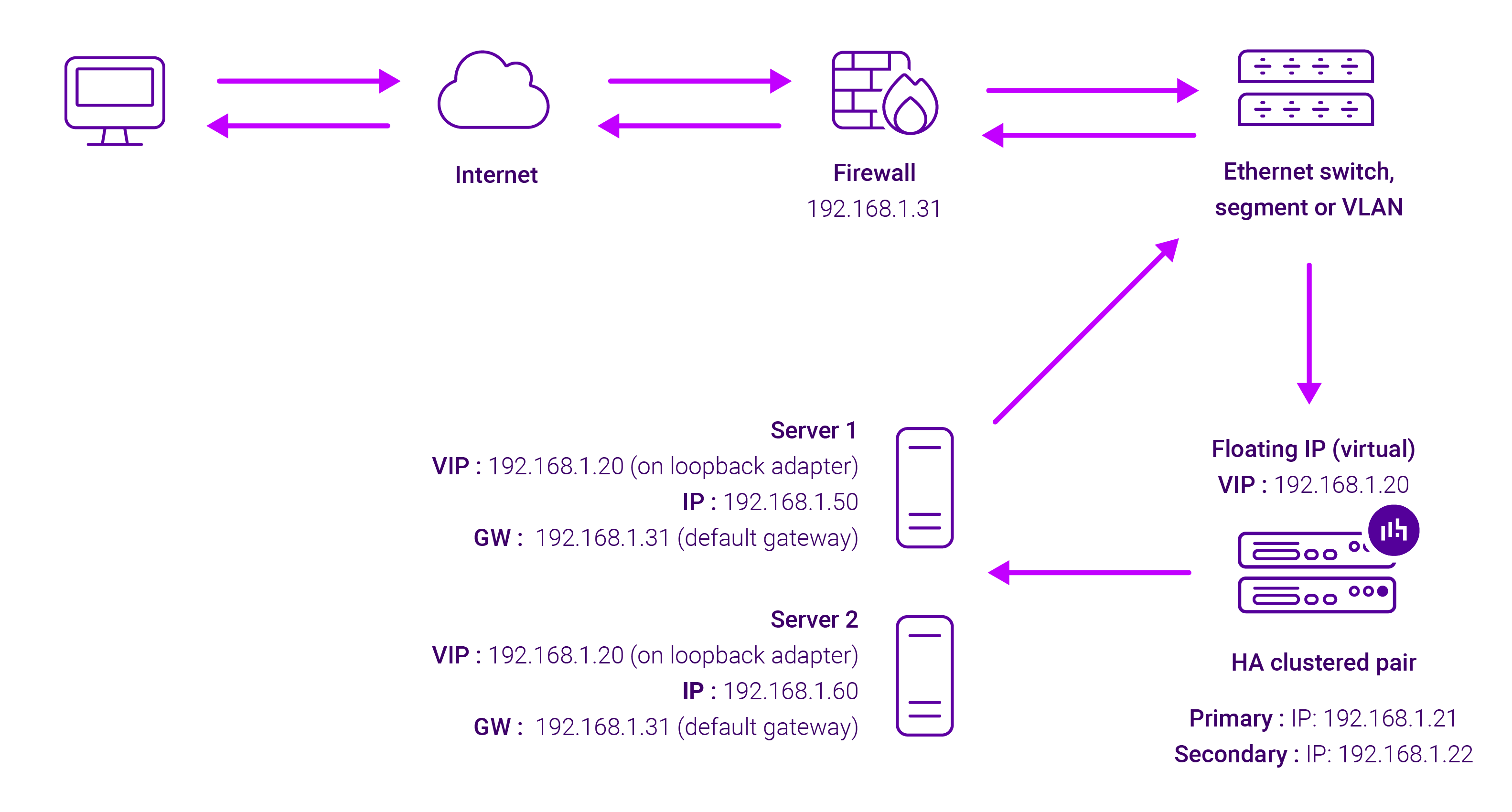
Layer 4 DR (Direct Routing) mode is a very high performance solution that requires little change to your existing infrastructure. The image below shows an example network diagram for this mode.
| Kemp, Brocade, Barracuda & A10 Networks call this Direct Server Return and F5 call it nPath. |
-
DR mode works by changing the destination MAC address of the incoming packet to match the selected Real Server on the fly which is very fast.
-
When the packet reaches the Real Server it expects the Real Server to own the Virtual Services IP address (VIP). This means that each Real Server (and the load balanced application) must respond to both the Real Server’s own IP address and the VIP.
-
The Real Server should not respond to ARP requests for the VIP. Only the load balancer should do this. Configuring the Real Server in this way is referred to as "Solving the ARP Problem". For more information please refer to DR Mode Considerations.
-
On average, DR mode is 8 times quicker than NAT mode for HTTP and much faster for other applications such as Remote Desktop Services, streaming media and FTP.
-
The load balancer must have an interface in the same subnet as the Real Servers to ensure layer 2 connectivity which is required for DR mode to operate.
-
The VIP can be brought up on the same subnet as the Real Servers or on a different subnet provided that the load balancer has an interface in that subnet.
-
Port translation is not possible with DR mode, e.g. VIP:80 → RIP:8080 is not supported.
-
DR mode is transparent, i.e. the Real Server will see the source IP address of the client.
Layer 4 DNAT Mode
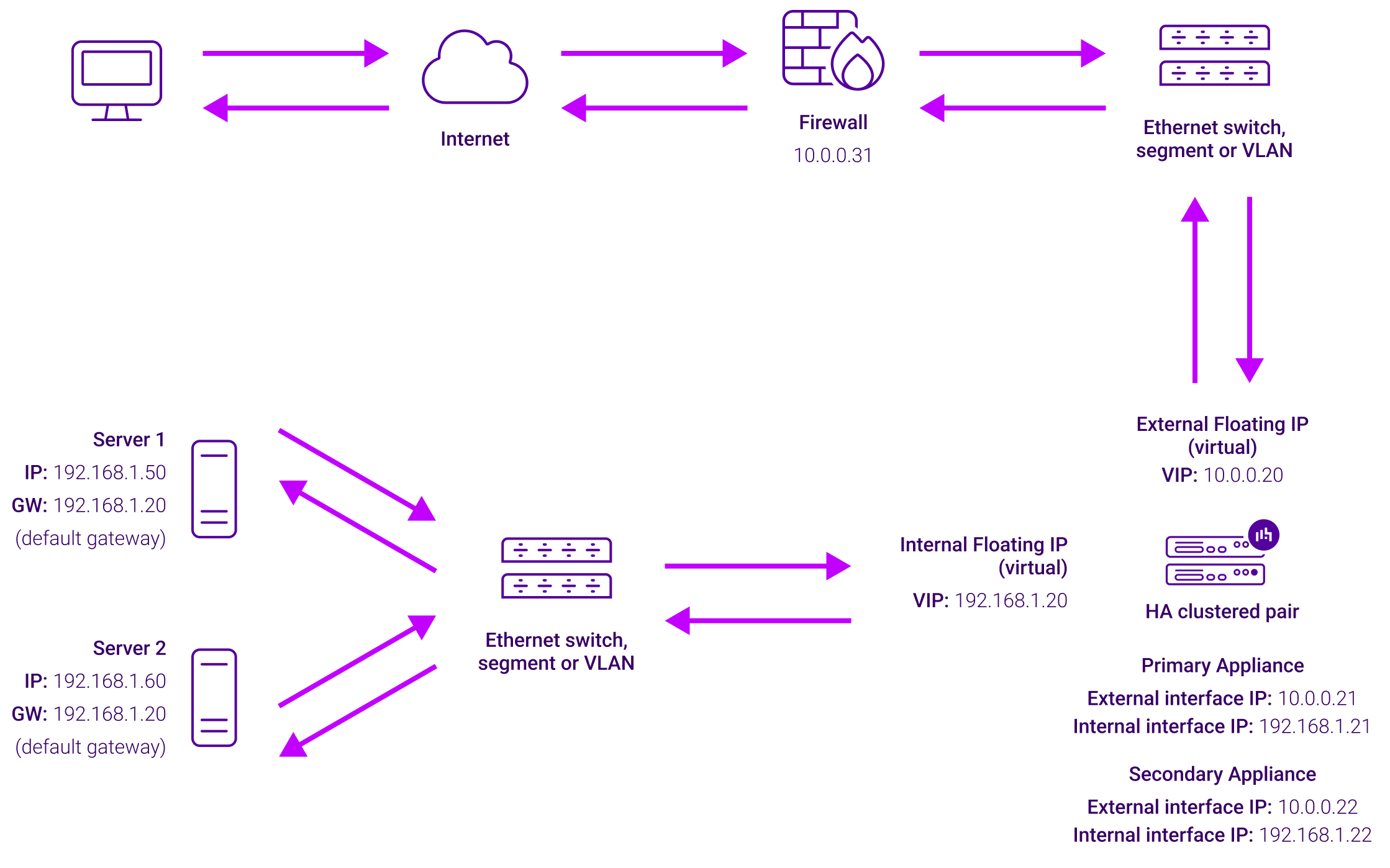
Layer 4 NAT mode is a high performance solution, although not as fast as layer 4 DR mode. This is because real server responses must flow back to the client via the load balancer rather than directly as with DR mode. The image below shows an example network diagram for this mode.
-
The load balancer translates all requests from the Virtual Service to the Real Servers.
-
NAT mode can be deployed in the following ways:
-
Two-arm (using 2 Interfaces) (as shown above) - Here, 2 subnets are used. The VIP is located in one subnet and the load balanced Real Servers are located in the other. The load balancer requires 2 interfaces, one in each subnet.
This can be achieved by using two network adapters, or by creating VLANs on a single adapter. -
Normally eth0 is used for the internal network and eth1 is used for the external network, although this is not mandatory since any interface can be used for any purpose.
-
If the Real Servers require Internet access, Auto-NAT should be enabled using the WebUI menu option: Cluster Configuration > Layer 4 - Advanced Configuration, the external interface should be selected.
-
The default gateway on the Real Servers must be set to be an IP address on the load balancer.
For an HA clustered pair, a floating IP should be added to the load balancer and used as the Real Server’s default gateway. This ensures that the IP address can "float" (move) between Primary and Secondary appliances. -
Clients can be located in the same subnet as the VIP or any remote subnet provided they can route to the VIP.
-
-
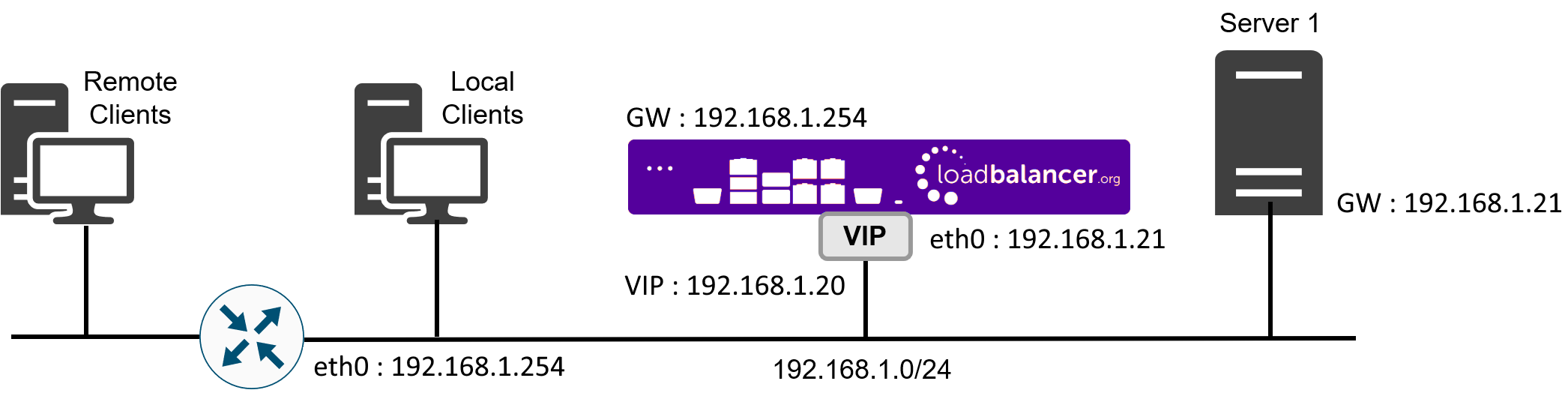
One-arm (using 1 Interface) - Here, the VIP is brought up in the same subnet as the Real Servers.
-
To support remote clients, the default gateway on the Real Servers must be an IP address on the load balancer and routing on the load balancer must be configured so that return traffic is routed back via the router.
For an HA clustered pair, a floating IP should be added to the load balancer and used as the Real Server’s default gateway. This ensures that the IP address can "float" (move) between Primary and Secondary appliances. -
To support local clients, return traffic would normally be sent directly to the client bypassing the load balancer which would break NAT mode. To address this, the routing table on the Real Servers must be modified to force return traffic to go via the load balancer. For more information please refer to One-Arm (Single Subnet) NAT Mode.
-
-
-
If you want Real Servers to be accessible on their own IP address for non-load balanced services, e.g. RDP, you will need to setup individual SNAT and DNAT firewall script rules for each Real Server or add additional VIPs for this.
-
Port translation is possible with Layer 4 NAT mode, e.g. VIP:80 → RIP:8080 is supported.
-
NAT mode is transparent, i.e. the Real Server will see the source IP address of the client.
NAT Mode Packet re-Writing
In NAT mode, the inbound destination IP address is changed by the load balancer from the Virtual Service IP address (VIP) to the Real Server. For outbound replies the load balancer changes the source IP address of the Real Server to be the Virtual Services IP address.
The following table shows an example NAT mode setup:
| Protocol | VIP | Port | RIP | Port |
|---|---|---|---|---|
TCP |
10.0.0.20 |
80 |
192.168.1.50 |
80 |
In this simple example all traffic destined for IP address 10.0.0.20 on port 80 is load-balanced to the real IP address 192.168.1.50 on port 80.
Packet rewriting works as follows:
1) The incoming packet for the web server has source and destination addresses as:
Source |
x.x.x.x:34567 |
Destination |
10.0.0.20:80 |
2) The packet is rewritten and forwarded to the backend server as:
Source |
x.x.x.x:34567 |
Destination |
192.168.1.50:80 |
3) Replies return to the load balancer as:
Source |
192.168.1.50:80 |
Destination |
x.x.x.x:34567 |
4) The packet is written back to the VIP address and returned to the client as:
Source |
10.0.0.20:80 |
Destination |
x.x.x.x:34567 |
Layer 4 SNAT Mode
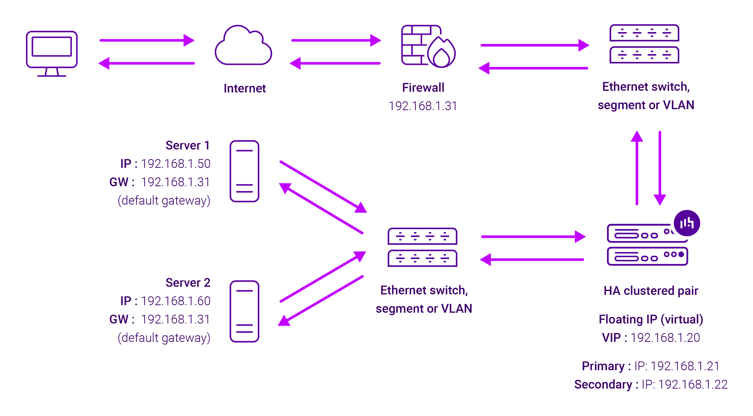
Layer 4 SNAT mode is a high performance solution, although not as fast as Layer 4 NAT mode or Layer 4 DR mode. The image below shows an example network diagram for this mode.
-
Real Servers in the cluster can be on any accessible network including across the Internet or WAN.
-
Layer 4 SNAT mode is not transparent, an iptables SNAT rule translates the source IP address to be the load balancer rather than the original client IP address.
-
Layer 4 SNAT mode can be deployed using either a one-arm or two-arm configuration. For two-arm deployments, eth1 is typically used for client side connections and eth0 is used for Real Server connections, although this is not mandatory since any interface can be used for any purpose.
-
Requires no mode-specific configuration changes to the load balanced Real Servers.
-
Port translation is possible with Layer 4 SNAT mode, e.g. VIP:80 → RIP:8080 is supported.
-
You should not use the same RIP:PORT combination for layer 4 SNAT mode VIPs and layer 7 SNAT mode VIPs because the required firewall rules conflict.
Layer 7 SNAT Mode
Layer 7 SNAT mode uses a proxy (HAProxy) at the application layer. Inbound requests are terminated on the load balancer and HAProxy generates a new corresponding request to the chosen Real Server. As a result, Layer 7 is typically not as fast as the Layer 4 methods. Layer 7 is typically chosen when either enhanced options such as SSL termination, cookie based persistence, URL rewriting, header insertion/deletion etc. are required, or when the network topology prohibits the use of the layer 4 methods. The image below shows an example network diagram for this mode.
-
Because layer 7 SNAT mode is a full proxy, Real Servers in the cluster can be on any accessible network including across the Internet or WAN.
-
Layer 7 SNAT mode is not transparent by default, i.e. the Real Servers will not see the source IP address of the client, they will see the load balancer’s own IP address by default, or any other local appliance IP address if preferred (e.g. the VIP address). This can be configured per layer 7 VIP. If required, the load balancer can be configured to provide the actual client IP address to the Real Servers in 2 ways. Either by inserting a header that contains the client’s source IP address, or by modifying the Source Address field of the IP packets and replacing the IP address of the load balancer with the IP address of the client. For more information on these methods please refer to Transparency at Layer 7.
-
Layer 7 SNAT mode can be deployed using either a one-arm or two-arm configuration. For two-arm deployments, eth1 is typically used for client side connections and eth0 is used for Real Server connections, although this is not mandatory since any interface can be used for any purpose.
-
Requires no mode-specific configuration changes to the load balanced Real Servers.
-
Port translation is possible with Layer 7 SNAT mode, e.g. VIP:80 → RIP:8080 is supported.
-
You should not use the same RIP:PORT combination for layer 7 SNAT mode VIPs and layer 4 SNAT mode VIPs because the required firewall rules conflict.
| For detailed configuration examples using various modes, see [Chapter 10 - Configuration Examples]. |
Which Load Balancing Method Should I Use?
Mode Summary
Layer 4 DR Mode - This mode offers the best performance and requires limited physical Real Server changes. The load balanced application must be able to bind to the Real Server’s own IP address and the VIP at the same time. This mode requires the "ARP Problem" to be solved, for more details please refer to DR Mode Considerations. Layer 4 DR mode is transparent, i.e. the Real Servers will see the source IP address of the client.
Layer 4 DNAT Mode - This mode is also a high performance solution but not as fast as DR mode. It requires the default gateway of each Real Server to be the load balancer and supports both one-arm and two-arm configurations. Layer 4 NAT mode is transparent, i.e. the Real Servers will see the source IP address of the client.
Layer 4 SNAT Mode - This mode is also a high performance solution but not as fast as the other layer 4 modes. It does not require any changes to the Real Servers and can be deployed in one-arm or two-arm mode. This mode is ideal for example when you want to load balance both TCP and UDP but you’re unable to use DR mode or NAT mode due to network topology or Real Server related reasons. Layer 4 SNAT mode is non-transparent, i.e. the Real Servers will see the source IP address of the load balancer.
Layer 7 SNAT Mode - This mode offers greater flexibility but at lower performance levels. It supports HTTP cookie insertion, RDP cookies, Connection Broker integration and directly supports SSL termination or can forward traffic to STunnel or Pound if preferred. It also enables URL rewriting and header manipulation rules to be implemented. It does not require any changes to the Real Servers and can be deployed in either one-arm or two-arm mode. HAProxy is a high performance solution, but since it operates as a full proxy at layer 7 it cannot perform as fast as the layer 4 methods. Layer 7 SNAT mode is non-transparent by default, i.e. the Real Servers will see the source IP address of the load balancer rather than the client. This mode can be made transparent through the use of TProxy.
Our Recommendation
Where possible we recommend that Layer 4 Direct Routing (DR) mode is used. This mode offers the best possible performance since replies go directly from the Real Servers to the client, not via the load balancer. It’s also relatively simple to implement. Ultimately, the final choice does depend on your specific requirements and infrastructure.
| If you are using Microsoft Windows Real Servers, we recommend that NLB (Network Load Balancing) is disabled on all servers to ensure that this does not interfere with the operation of the load balancer. |