Additional Information
Further reading — deployment guides, related documentation, and how to contact support.
Server Feedback Agent
The load balancer can dynamically modify the weight of each Real Server by gathering data from either a custom feedback agent or a HTTP server. Reducing the weight of a server compared to others in the pool will reduce the amount of traffic it receives.
For layer 4 VIPs, both the agent and HTTP Server methods can be used, for Layer 7 VIPs, only the agent method is supported.
By default, the agent listens on TCP port 3333, although this can be changed if required.
A telnet to port 3333 on a Real Server with the agent installed returns the current idle value as an integer value between 0 and 100. By default, the idle value is based on current CPU utilization. This can also be based on RAM utilization and the number of current connections or a combination of all three.
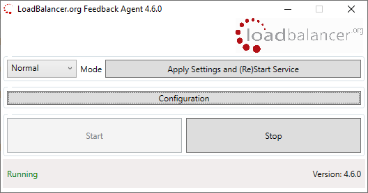
This can be configured by modifying the XML configuration file located in the agent’s installation folder - by default C:\ProgramData\LoadBalancer.org\LoadBalancer. The file can be edited directly or by clicking the Configuration button in the agent monitor program - see "Controlling the Agent" below.
The load balancer uses the formula (idle value/100) * initial weight to find the new dynamic weight.
|
The "initial weight" is the weight set in the WebUI for each Real Server. For more information about the feedback agent, please refer to this blog. |
Windows Agent
The latest Windows feedback agent (v4.6.0) can be downloaded here.
Linux/Unix Agent
The Linux feedback agent files can be downloaded using the following links:
readme file: https://downloads.loadbalancer.org/agent/linux/v4.1/readme.txt
xinetd file: https://downloads.loadbalancer.org/agent/linux/v4.1/lb-feedback
feedback script: https://downloads.loadbalancer.org/agent/linux/v4.1/lb-feedback.sh
Installation & Testing
Install xinetd - if not already installed:
apt-get install xinetd
Insert the following line into /etc/services:
lb-feedback 3333/tcp # Loadbalancer.org feedback daemon
Then run the following commands:
cp lb-feedback.sh /usr/bin/lb-feedback.sh
chmod +x /usr/bin/lb-feedback.sh
cp lb-feedback /etc/xinetd.d/lb-feedback
chmod 644 /etc/xinetd.d/lb-feedback
/etc/init.d/xinetd restart
To test the agent:
telnet 127.0.0.1 3333
Trying 127.0.0.1...
Connected to 127.0.0.1.
Escape character is '^]'.
95%
Connection closed by foreign host.
| The agent files must be installed on each Real Server. |
HTTP Server
You can use any HTTP server responding on port 3333 to give feedback information to the load balancer. The format of this information must be an integer number of 0-100 without any header information. Using this method, you can generate a custom response based on your application’s requirements. Unresolved include directive in modules/admin/pages/additional-information.adoc - include::partial$front-and-rear-panel-layouts.adoc[]
IPMI Configuration
The Enterprise Prime includes Intelligent Platform Management Interface (IPMI) which provides remote management and control.
IPMI Network Settings
IPMI can be accessed via the dedicated IPMI Ethernet interface or via one of the standard Ethernet interfaces in shared/bridged mode.
To use the dedicated IPMI interface, ensure that a network cable is plugged into the interface before powering up the appliance.
By default, the appliance attempts to use DHCP to obtain an IP address for IPMI. If a DHCP server is not available, the IP address must be set manually.
A static IP address can be assigned using the boot mode Setup Utility or by using the IPMI Web Interface.
Using the Setup Utility
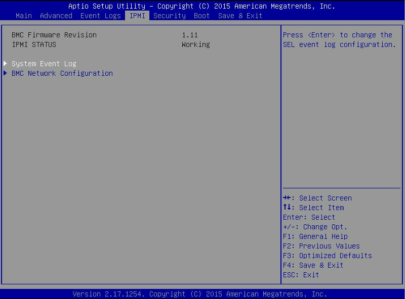
To access the IPMI configuration menu via the Setup Utility, hit <DEL> at boot time, then select the IPMI menu:
Select the BMC Network Configuration option and change Update IPMI LAN Configuration to Yes, all network settings can then be configured:
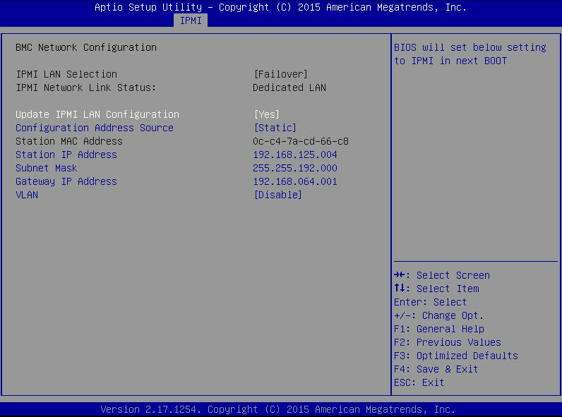
| Depending on the particular IPMI version, the option to change the IPMI LAN interface may be greyed out as shown above. In this case, use the IPMI Web Interface (see below) to configure this setting. |
To configure the IP address and other network settings:
-
Set Configuration Address Source to Static.
-
Configure the IP address, Subnet Mask and other network settings as required.
To exit the IPMI configuration menu, hit <ESC>.
To save any changes, select the Save & Exit menu, then select Save Changes and Reset to save and apply the new settings.
Using the IPMI Web Interface
Once the network is configured, the IPMI Web Interface can be accessed using a web browser:
https://<IPMI IP address>
The default user credentials to access the IPMI Web Interface are:
Username : ADMIN
Password : refer to the label on the appliance / packaging
| For older appliances, the password was set to "ADMIN". |
Once logged in, the IPMI Web Interface can be used to monitor and configure the system, configure all IPMI settings and access the Remote Console.
Technical Support / More Information
If you have any questions, please contact support@loadbalancer.org.
For more information, refer to the IPMI User Guide.
iDRAC Configuration
All Dell based hardware appliances shipped since January 2024 include an integrated Dell Remote Access Controller (iDRAC) Enterprise license which enables remote monitoring and remote control of the appliance. Details of all supported iDRAC features are available here.
iDRAC Network Settings
iDRAC can be accessed via the dedicated iDRAC interface on the rear panel or by sharing one of the built in LAN On Motherboard (LOM) interfaces. Using the dedicated port ensures that iDRAC management traffic is separated from production workload.
By default, the appliance attempts to use DHCP to obtain an IP address. If a DHCP server is not available, the IP address is set to 192.168.0.120/255.255.255.0.
A static IP address can be assigned using System Setup or by using the iDRAC Web Interface.
Using System Setup
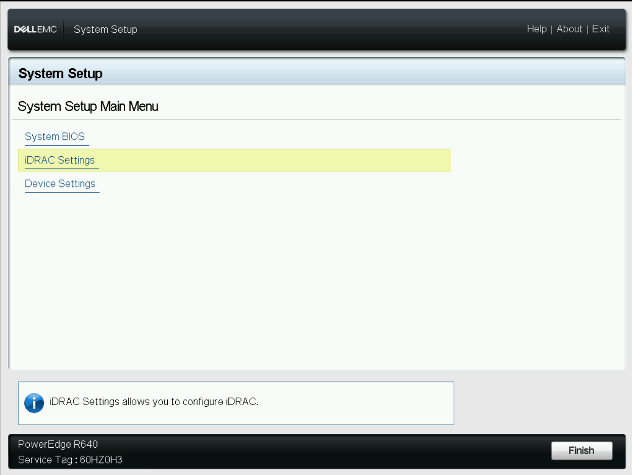
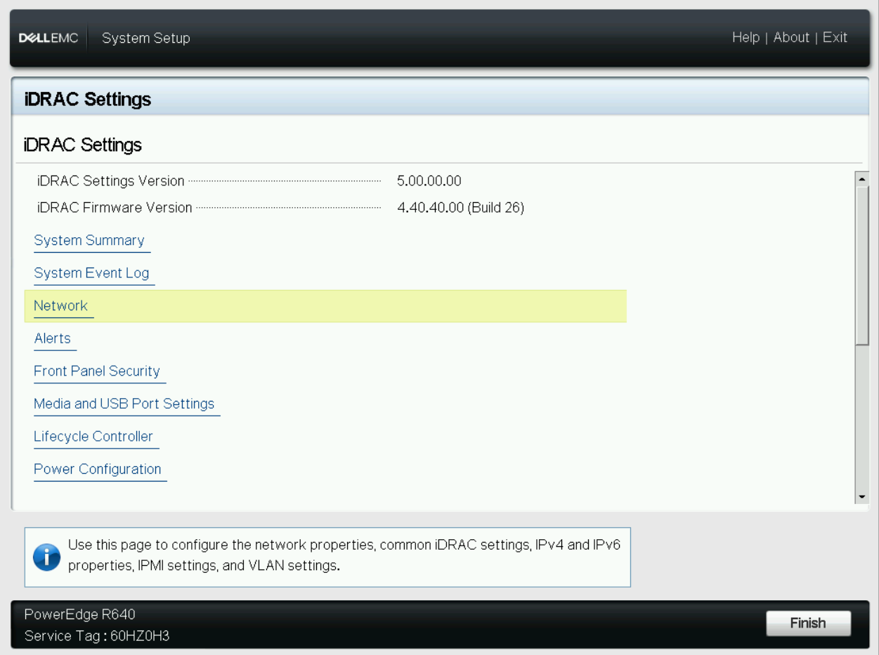
To access the iDRAC configuration menu via System Setup, hit <F2> at boot time, then select iDRAC Settings:
Select the Network option:
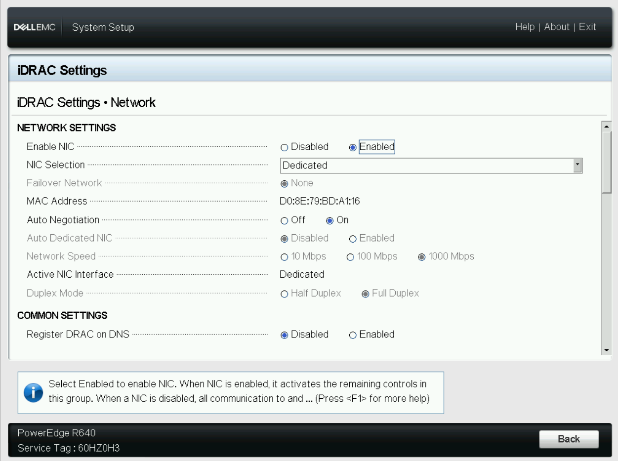
The iDRAC network can be enabled/disabled and the interface to use can be configured in the NETWORK SETTINGS section:
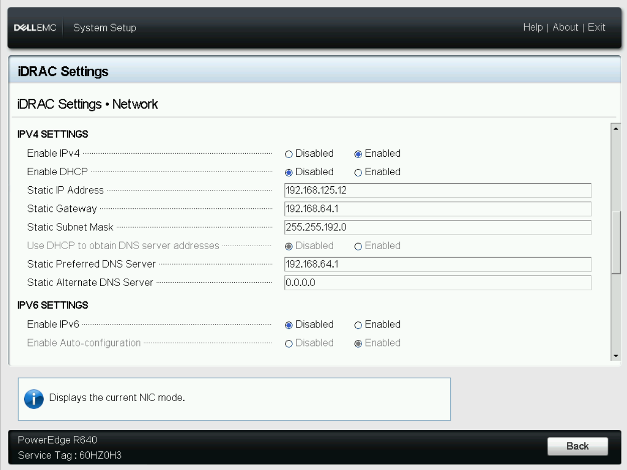
Scroll down to the IPV4 SETTINGS & IPV6 SETTINGS section to configure the IP address, subnet mask and other network settings:
| For additional information, see this Dell article. |
To exit the iDRAC configuration menu, click Back and click Finish. Click Finish again to exit System Setup.
If changes were made, you’ll be prompted to save them:
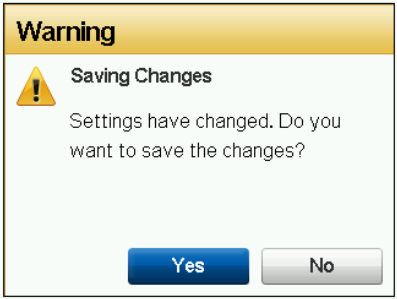
Click Yes to save the changes.
Using the iDRAC Web Interface
Once an iDRAC IP address is assigned, the iDRAC Web Interface can be accessed using a web browser:
https://<iDRAC IP address>
The default user credentials to access the iDRAC Web Interface are:
Username : root
Password : refer to the pull-out tab in the front of the appliance
Once logged in, the iDRAC Web Interface can be used to monitor and configure the system, configure all iDRAC settings and access the Virtual Console.
Technical Support / More Information
If you have any questions, please contact support@loadbalancer.org.
For more information, refer to the iDRAC User Guide.
Appliance IPv4 Address Format (CIDR notation)
When specifying IP addresses on the appliance, CIDR format is used. The following table shows the various masks and the corresponding IPv4 IP/CIDR equivalents:
| Subnet Mask | IP/CIDR Suffix |
|---|---|
255.255.255.255 |
a.b.c.d/32 |
255.255.255.254 |
a.b.c.d/31 |
255.255.255.252 |
a.b.c.d/30 |
255.255.255.248 |
a.b.c.d/29 |
255.255.255.240 |
a.b.c.d/28 |
255.255.255.224 |
a.b.c.d/27 |
255.255.255.192 |
a.b.c.d/26 |
255.255.255.128 |
a.b.c.d/25 |
255.255.255.000 |
a.b.c.d/24 |
255.255.254.000 |
a.b.c.d/23 |
255.255.252.000 |
a.b.c.d/22 |
255.255.248.000 |
a.b.c.d/21 |
255.255.240.000 |
a.b.c.d/20 |
255.255.224.000 |
a.b.c.d/19 |
255.255.192.000 |
a.b.c.d/18 |
255.255.128.000 |
a.b.c.d/17 |
255.255.000.000 |
a.b.c.d/16 |
255.254.000.000 |
a.b.c.d/15 |
255.252.000.000 |
a.b.c.d/14 |
255.248.000.000 |
a.b.c.d/13 |
255.240.000.000 |
a.b.c.d/12 |
255.224.000.000 |
a.b.c.d/11 |
255.192.000.000 |
a.b.c.d/10 |
255.128.000.000 |
a.b.c.d/9 |
255.000.000.000 |
a.b.c.d/8 |
254.000.000.000 |
a.b.c.d/7 |
252.000.000.000 |
a.b.c.d/6 |
248.000.000.000 |
a.b.c.d/5 |
240.000.000.000 |
a.b.c.d/4 |
224.000.000.000 |
a.b.c.d/3 |
192.000.000.000 |
a.b.c.d/2 |
128.000.000.000 |
a.b.c.d/1 |