System Configuration
Local Configuration
System date & time
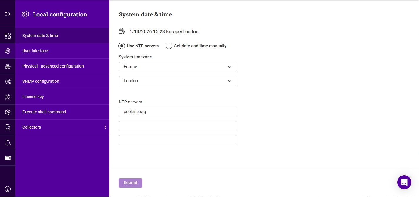
The system date and time can be configured automatically using NTP or set manually.
To configure NTP:
-
Using the WebUI, navigate to Local Configuration > System date & time.
-
Select Use NTP servers.
-
Select the required System timezone settings.
-
Specify the NTP servers. Both IP addresses and FQDNs can be used.
-
Click Submit.
To manually specify the date and time:
-
Select Set date and time manually.
-
Select the required System timezone settings.
-
Configure the Date and Time.
-
Click Submit.
User interface
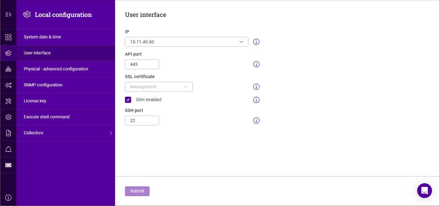
To configure user interface settings:
-
Using the WebUI, navigate to Local Configuration > User Interface.
-
Select the required IP address. The drop-down is populated with static IPs.
-
Set the required API/WebUI Port.
-
Select the required SSL Certificate.
-
If SSH access is required, check the SSH enabled checkbox and specify the SSH port.
Physical - advanced configuration
Hostname & domain
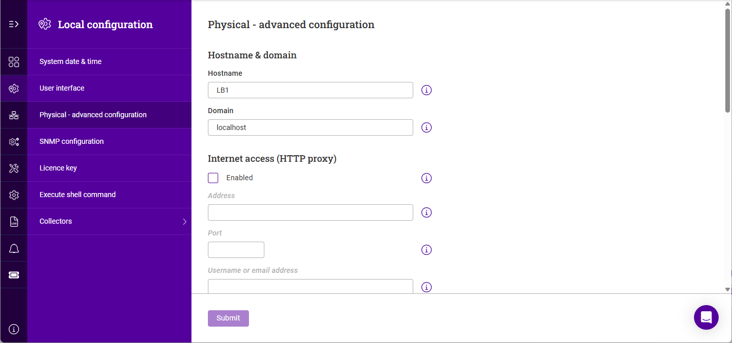
To configure the hostname and domain:
-
Using the WebUI, navigate to Local Configuration > Physical - advanced configuration.
-
Specify the Hostname and Domain.
-
Click Submit.
Internet access (HTTP proxy)
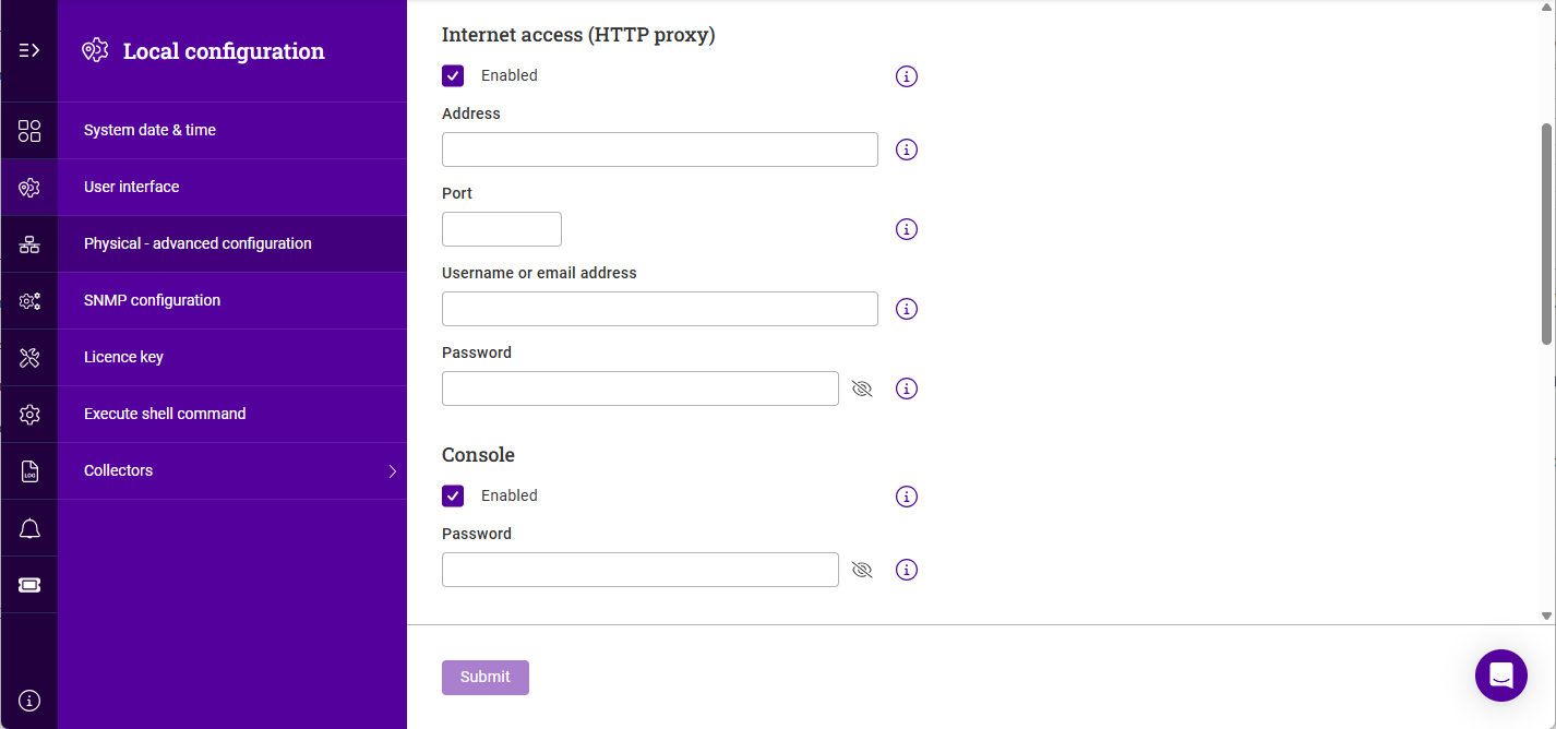
To configure a proxy server to use for Internet access:
-
Using the WebUI, navigate to Local Configuration > Physical - advanced configuration.
-
Scroll to the Internet access (HTTP proxy) section.
-
Enable (check) the Enabled checkbox.
-
Specifiy the Address of the proxy server. An IP address or FQDN can be used.
-
Specify the Port of the proxy server.
-
If authentication is used, specify the Username or email address and the Password.
-
Click Submit.
Console
To enable console & SSH access:
-
Using the WebUI, navigate to Local Configuration > Physical - advanced configuration.
-
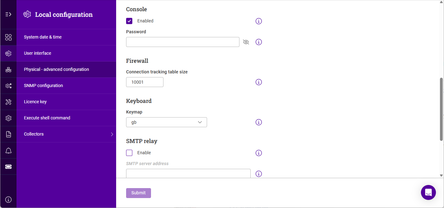
Scroll to the Console section.
-
Enable (check) the Enabled checkbox.
-
Specifiy a Password for the "loadbalancer" user.
-
Click Submit.
Firewall
To set the firewall connection tracking table size:
-
Using the WebUI, navigate to Local Configuration > Physical - advanced configuration.
-
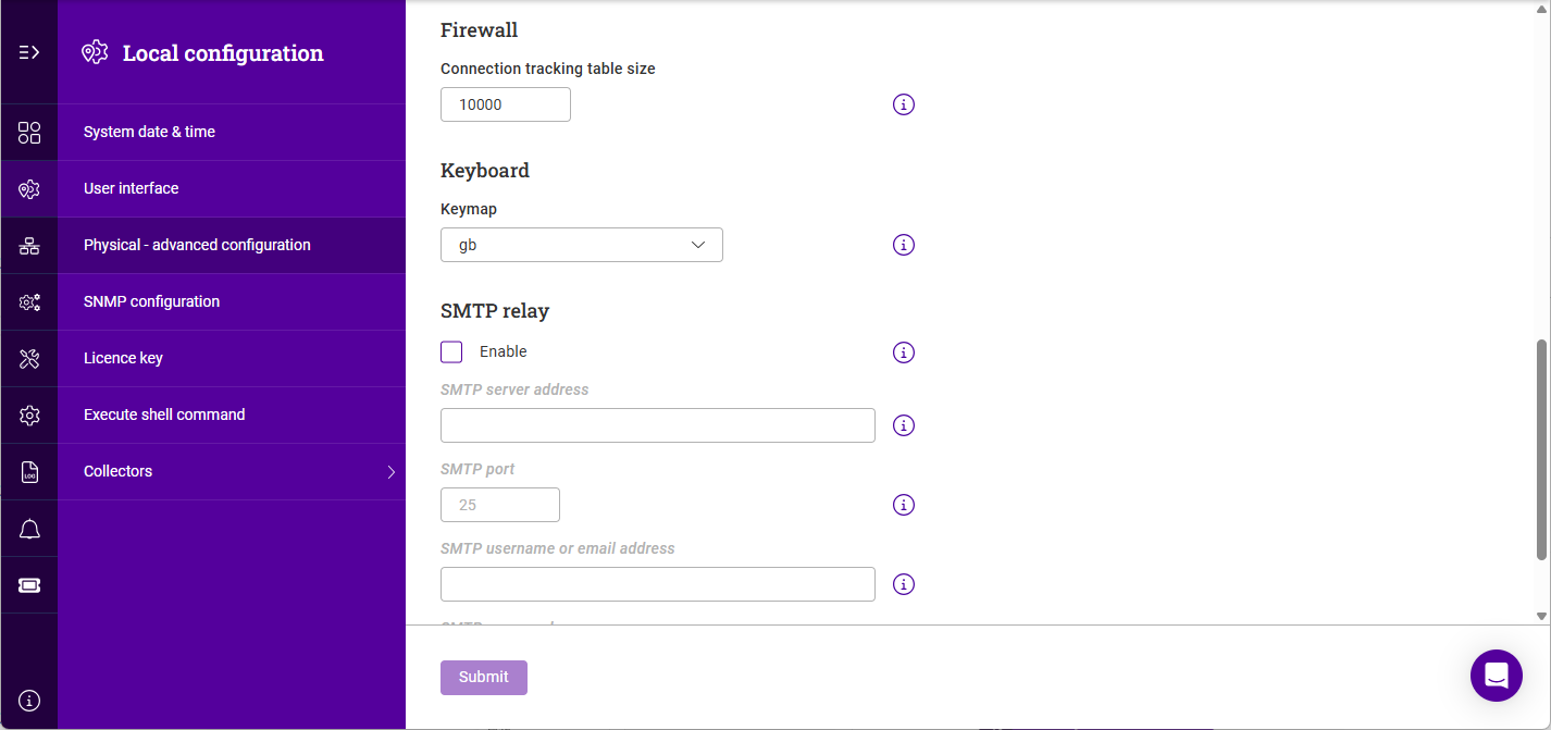
Scroll to the Firewall section.
-
Specify the Connection tracking table size.
-
Click Submit.
Keyboard
-
Using the WebUI, navigate to Local Configuration > Physical - advanced configuration.
-
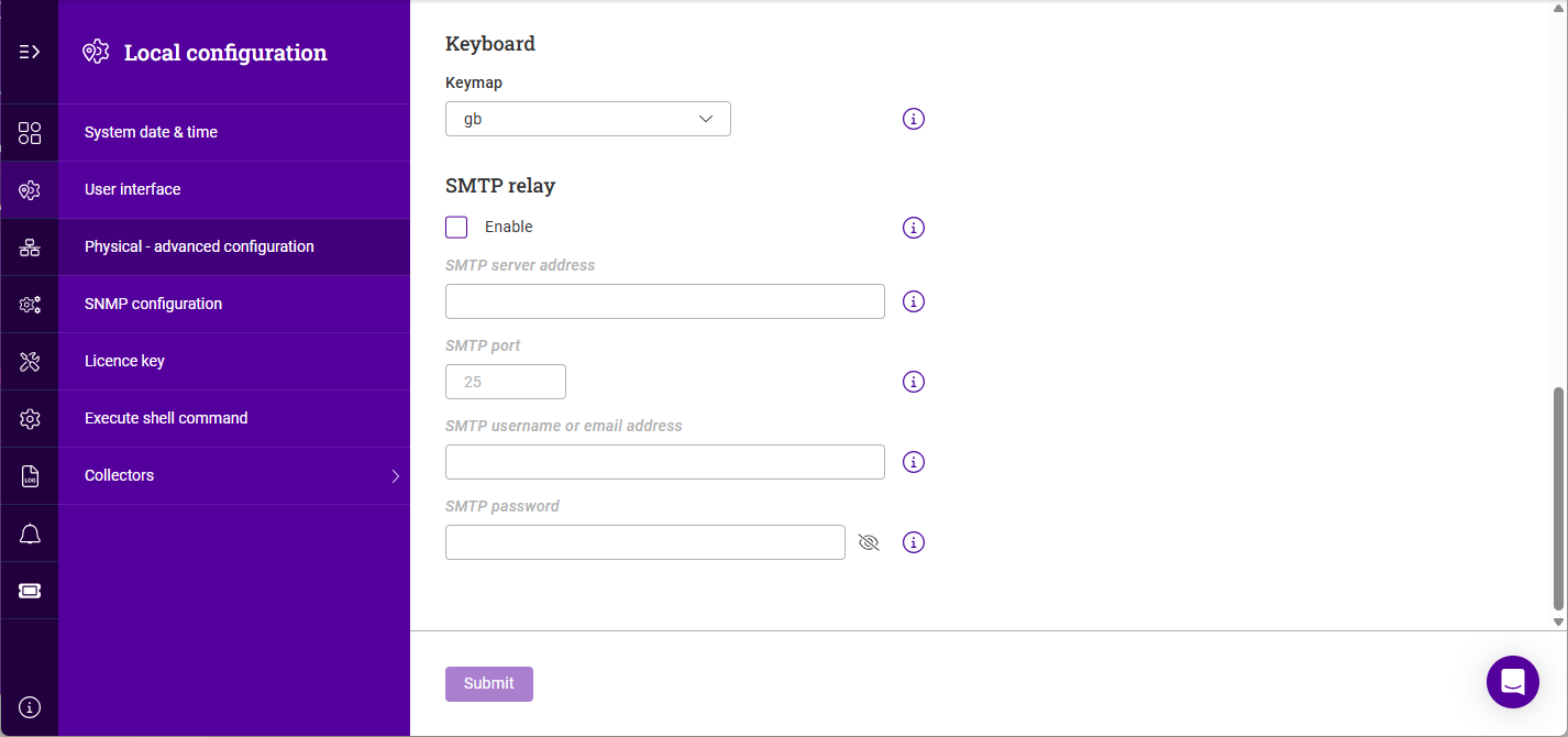
Scroll to the Keyboard section.
-
Select the required Keymap.
-
Click Submit.
SMTP relay
To configure an SMTP relay server:
-
Using the WebUI, navigate to Local Configuration > Physical - advanced configuration.
-
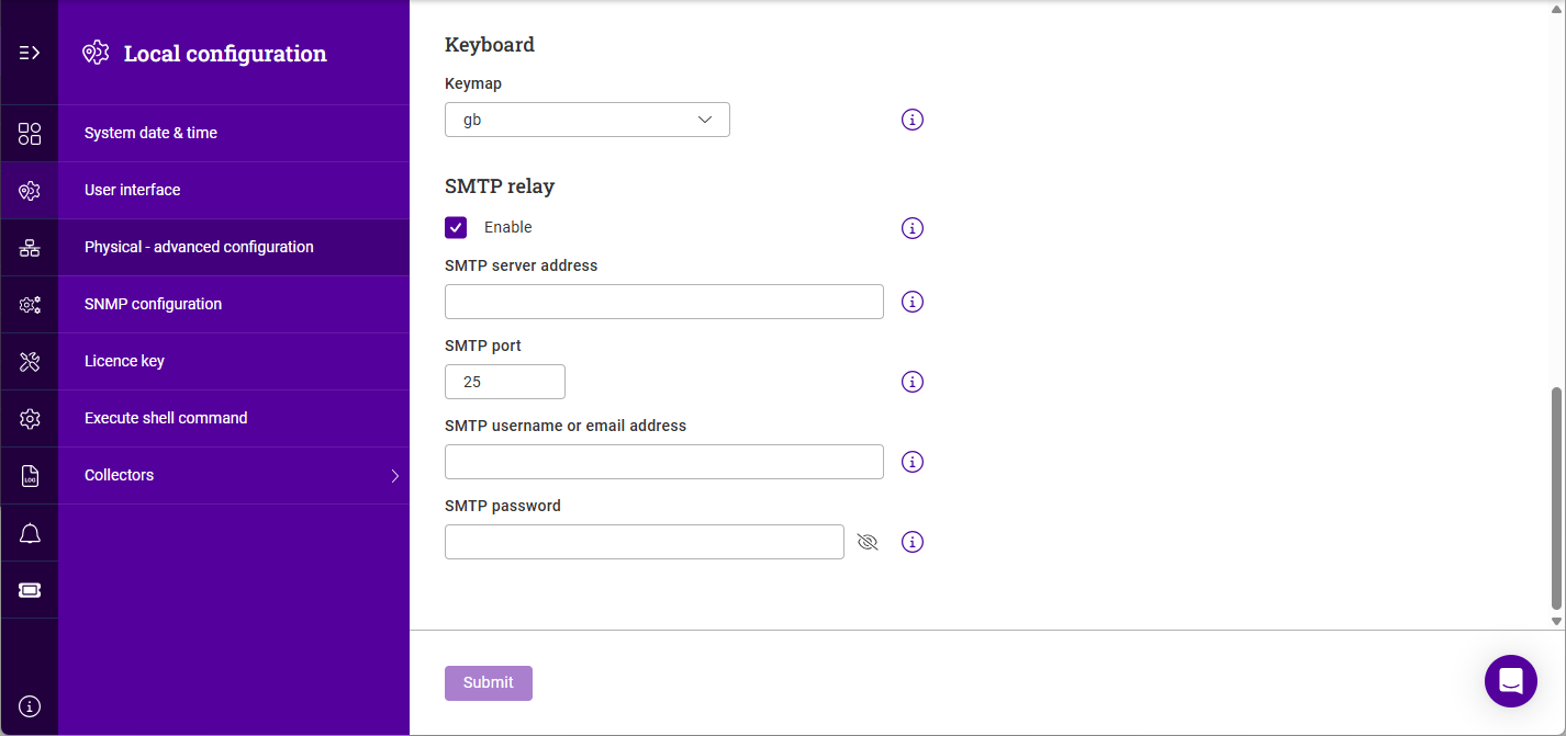
Scroll to the SMTP Relay section.
-
Enable (check) the Enabled checkbox.
-
Specifiy the SMTP server address of the relay server. An IP address or FQDN can be used.
-
Specify the SMTP port of the relay server.
-
If authentication is used, specify the SMTP username or email address and the SMTP Password.
-
Click Submit.
SNMP Configuration
| A [Service IP] must be available first before configuring SNMP. |
-
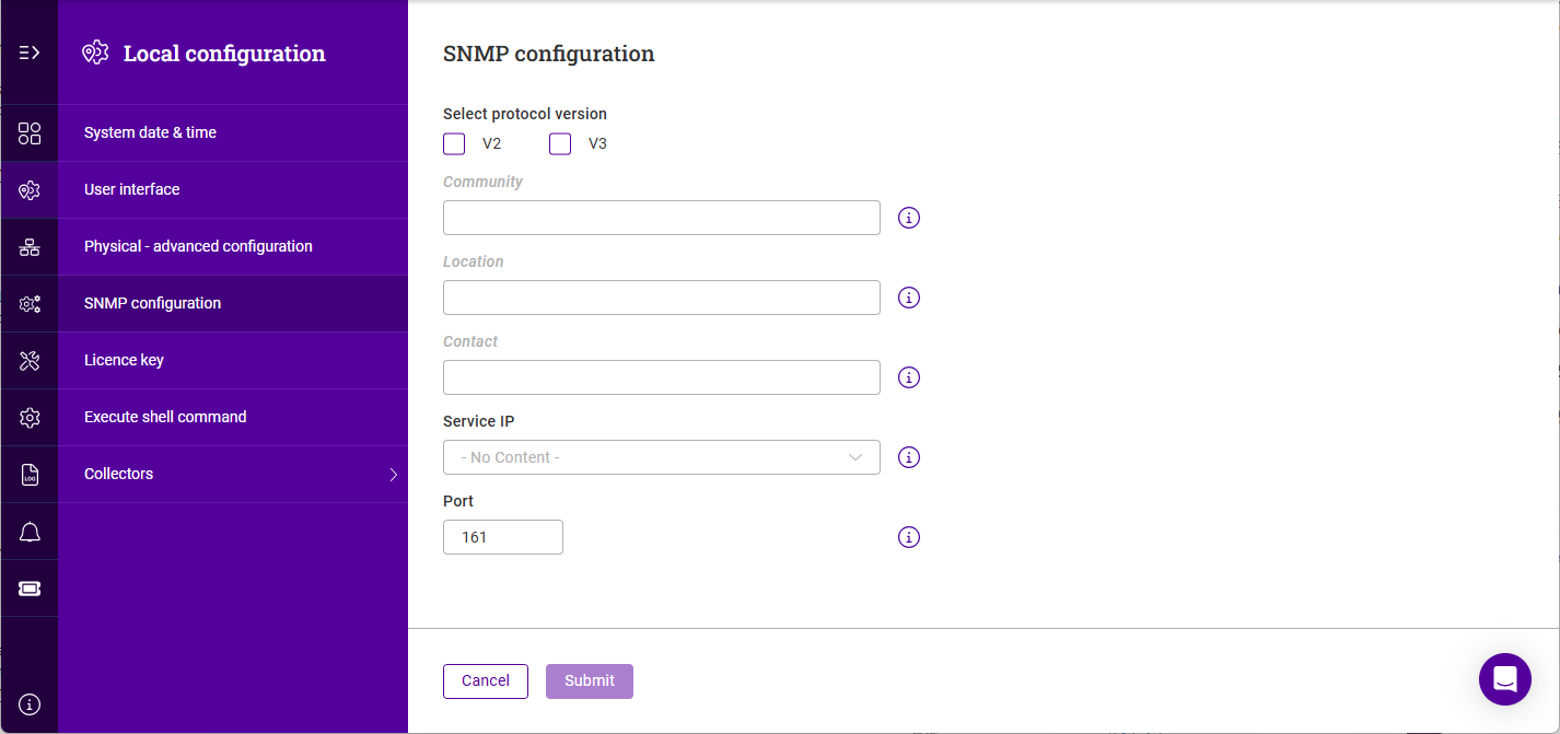
Using the WebUI, navigate to Local Configuration > SNMP configuration.
-
Click Add SNMP Settings.
-
Select the relevant SNMP version number(s).
-
Specify the Community string (SNMP V2 only), Location and Contact.
-
Select the Service IP from the dropdown and specify the required Port.
-
Click Submit.
Installing the License Key
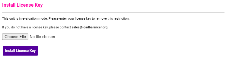
The appliance can be used completely unrestricted for 30 days without installing a license key. After 30 days, the appliance continues to work but it’s no longer possible to make configuration changes.
| if you’re conducting a PoC (Proof of Concept) using the VA and require more time to complete your evaluation, please contact sales@loadbalancer.org who will be able to provide guidance on how to extend the trial. |
For an unlicensed VA, the following message is displayed:

For an unlicensed hardware appliance, the following message is displayed:

To apply the license key:
-
Using the WebUI, navigate to: Local Configuration > License Key.
-
Enter the licence key as shown above.
-
Click Submit.
Format is : @license key@
| Once the license is applied, these warning messages will no longer be displayed. |
Execute shell command
-
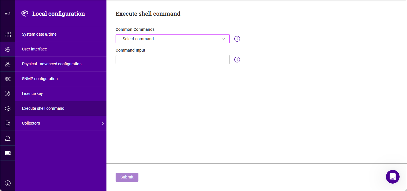
Using the WebUI, navigate to Local Configuration > Execute shell command.
-
Either select a Common Command from the dropdown or enter your own using the Command input field.
-
Click Submit to run the command. Command output will be displayed in the area below the Command input field.
Collectors
Prometheus
The Prometheus collector can provide both Layer 7 (HAProxy) and local node metrics.
To enable the Prometheus Collector:
| A [Service IP] must be available first before configuring Prometheus. |
-
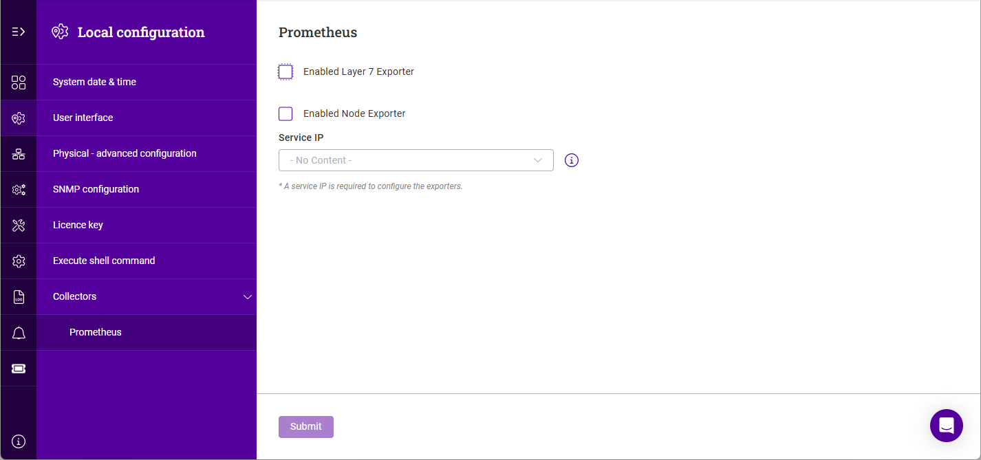
Using the WebUI, navigate to Local Configuration > Collectors > Prometheus.
-
Enable (check) the Enabled Layer 7 Exporter checkbox to provide Layer 7 metrics.
-
Update the Exporter port if required.
-
Enable (check) the Enabled Node Exporter checkbox to provide local node metrics.
-
Update the Exporter port if required.
-
Select the required Service IP.
-
Click Submit.
Portal management - NOTE - currently disabled in teh ISO image
The Loadbalancer.org ADC Portal is an ultra-secure, cloud-based ADC management platform that enables ADCs from Loadbalancer.org and multiple other vendors including F5, Citrix Netscaler and Progress Kemp to be monitored and managed. This enables centrally controlled backups, software updates, real-time security alerts (CVEs) and secure remote access for all connected ADCs. To add an appliance to the Portal, follow the steps below.
Step 1 - Configure Portal Connection Details
Step 2 - Start the Appliance Adoption Process
Step 3 - Adopt the Shuttle
Step 4 - Add the ADC to the Portal
-
Click LOADBALANCER | PORTAL in the Portal’s main menu bar to view the Dashboard.
-
In the ADCs panel:
-
If there are currently no ADCs, click Connect an ADC.
-
In the menu to the left, select List.
-
-
if ADCs have already been added, click View my ADCs.
-
-
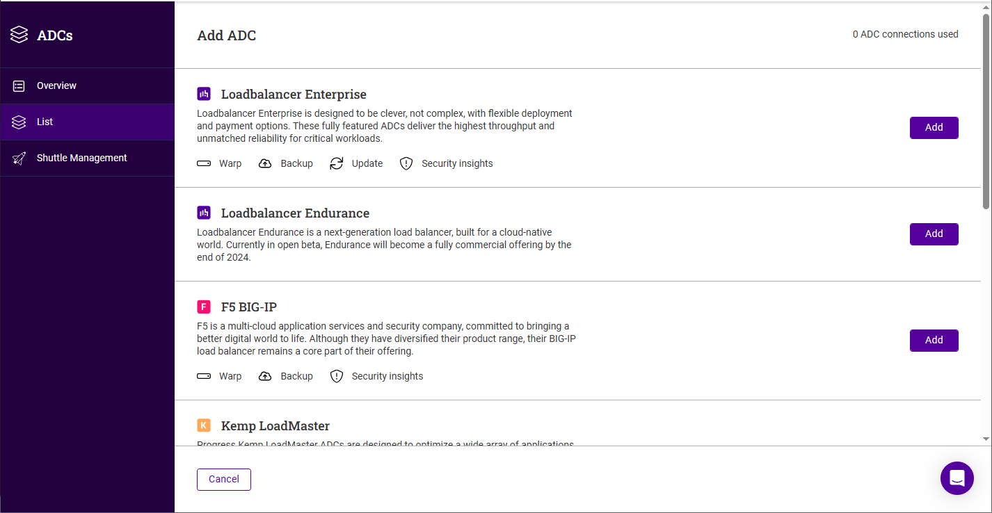
Click the Add ADC button.
-
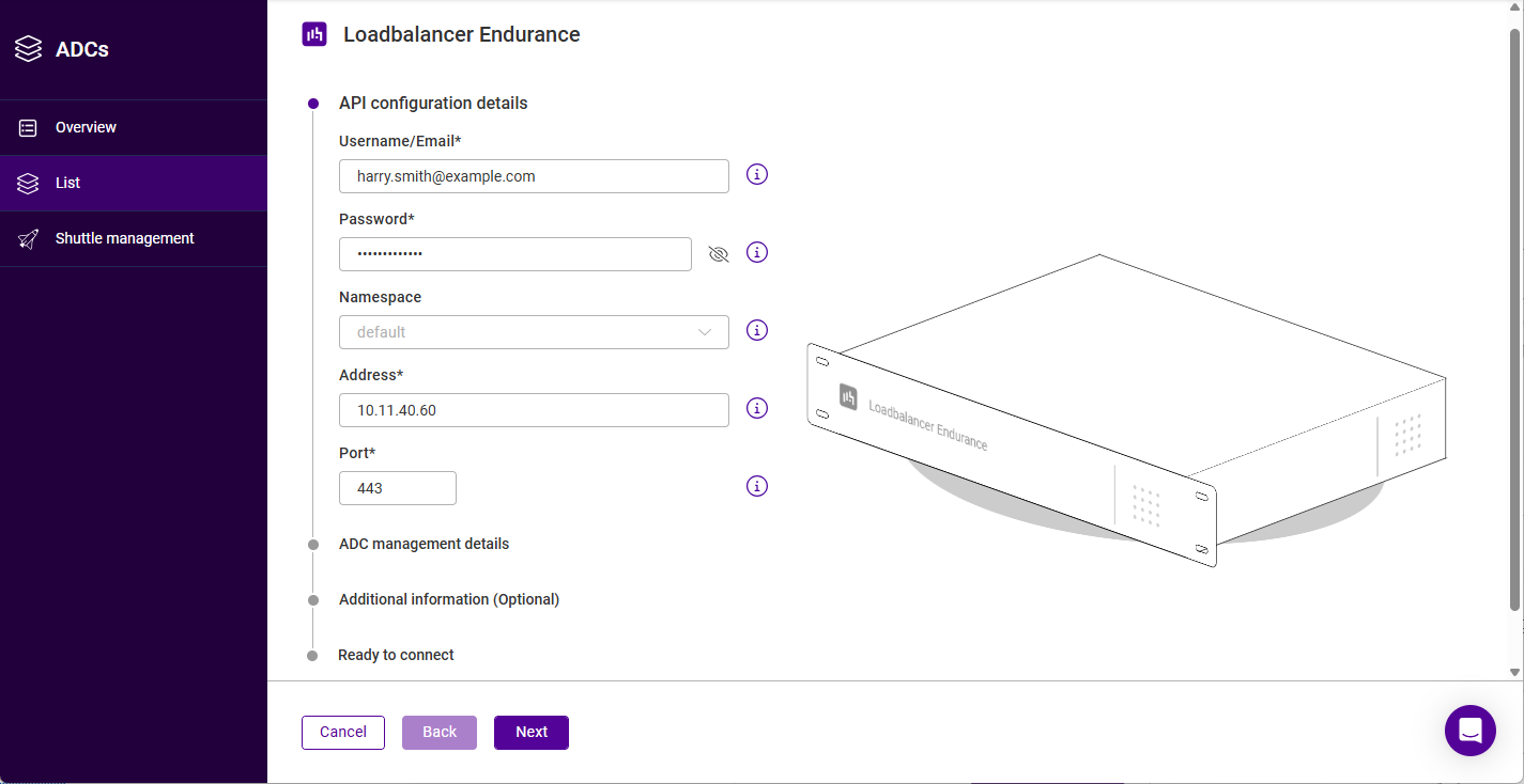
Click the Add button for Loadbalancer Endurance.
-
Specify the Username/Email and Password for a valid Endurance user.
-
Select the required Namespace.
-
Enter the IP address of the appliance being added.
-
Leave the Port set to the default value (443) unless this has been changed for the appliance being added.
-
Click Next.
-
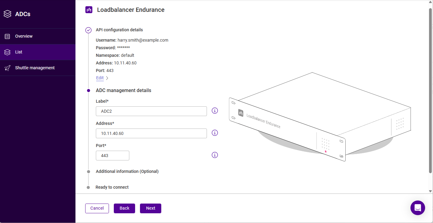
Enter an appropriate Label (name) for the appliance.
-
Ensure that the IP Address is correct.
-
Leave the Port set to the default value (443) unless this has been changed for the appliance being added.
-
Click Next.
-
Enter any required Notes and Tags to describe the appliance and click Next.
To create a tag, enter the required name and hit Enter. The tag will appear colored blue under the Tags field. Repeat to specify multiple tags (up to 30). -
Verify all settings, these can be changed if needed using the relevant Edit option.
-
Click Submit - if the details have been specified correctly, the appliance will appear in the list.
| The Portal connection method above uses a Shuttle and connection for each ADC. It’s also possible to configure a single dedicated Shuttle and use this for all ADCs. For more information, see the Portal Guide. |
Network Configuration
Interfaces
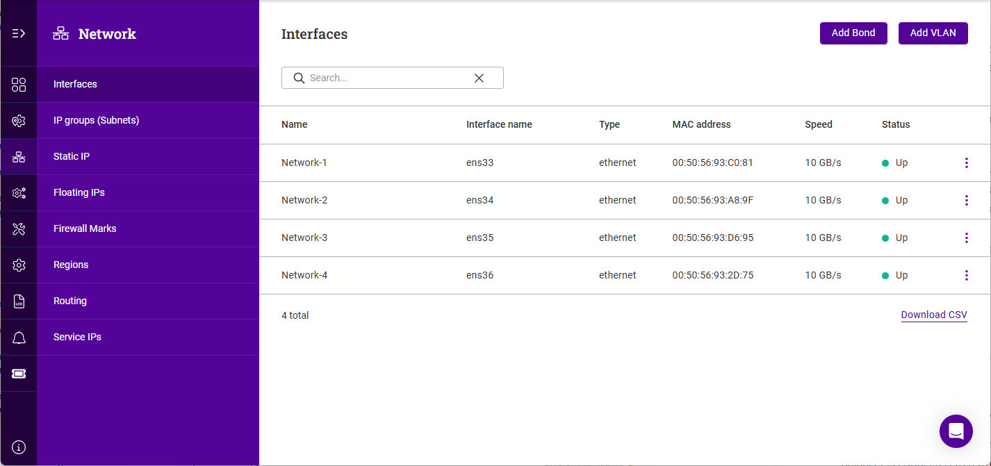
The appliance ships with 4 interfaces, each interface can be used for any purpose. IP Groups (Subnets) are created and associated with an interface, Static IPs and Floating IPs can then be created within each subnet. Multiple interfaces can be bonded if required, VLANs can be configured for an interface or bond. This architecture allows subnets/IP addresses to be easily moved between interfaces.
To view all interfaces:
-
Using the WebUI, navigate to Network > Interfaces.
To view/edit an interface:
-
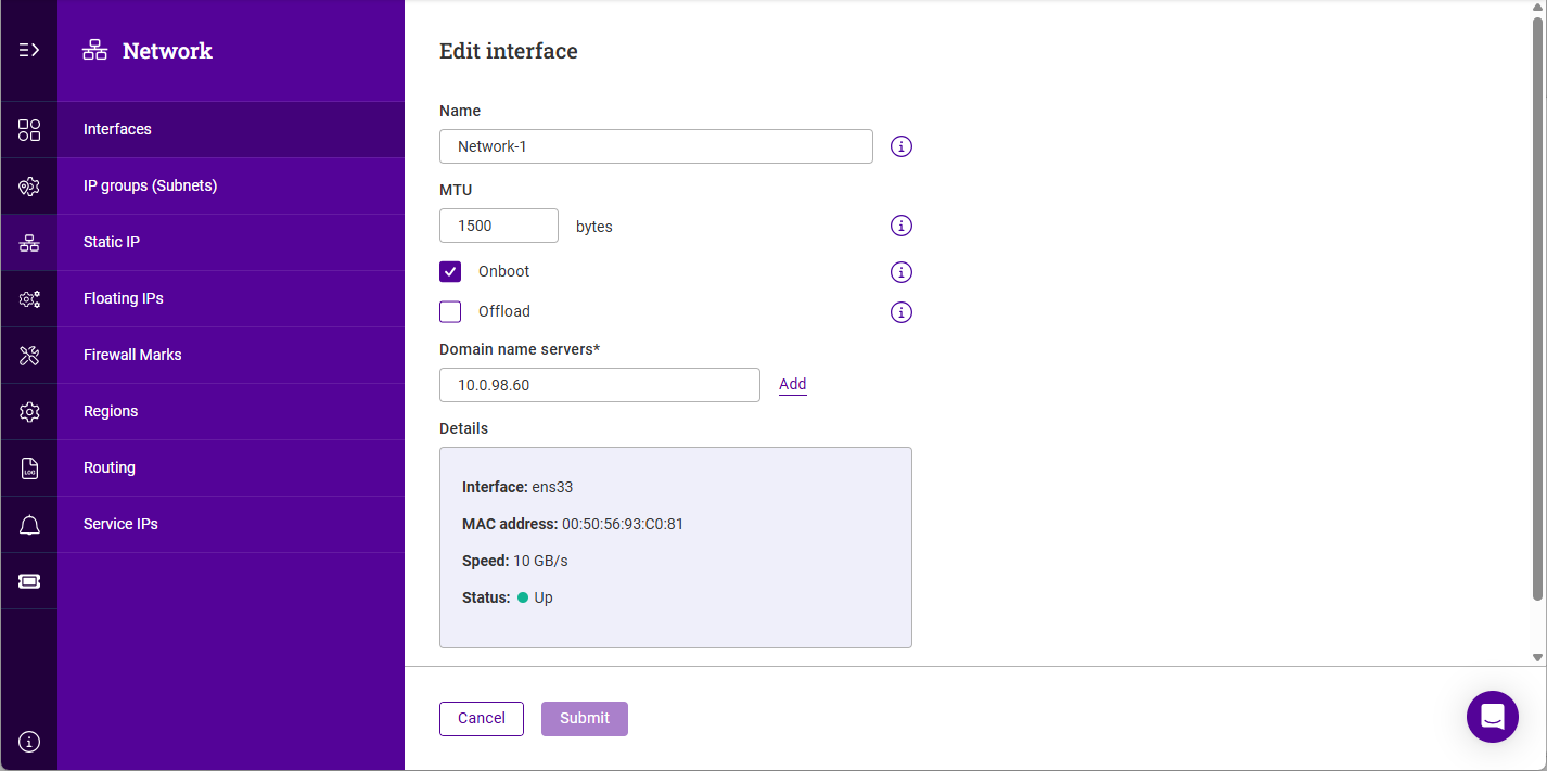
Click the three dots menu next to the Interface you’d like to view or edit.
-
Update the Name if required.
-
Update the MTU if required.
-
Enable (check) the Onboot checkbox to enable the interface on boot up.
-
Enable (check) the Offload checkbox to enable hardware NIC offloading (where available).
-
Configure the required Domain name servers for the interface.
-
Click Submit to save any changes.
Bonding
To Configure bonding:
-
Using the WebUI, navigate to Network > Interfaces.
-
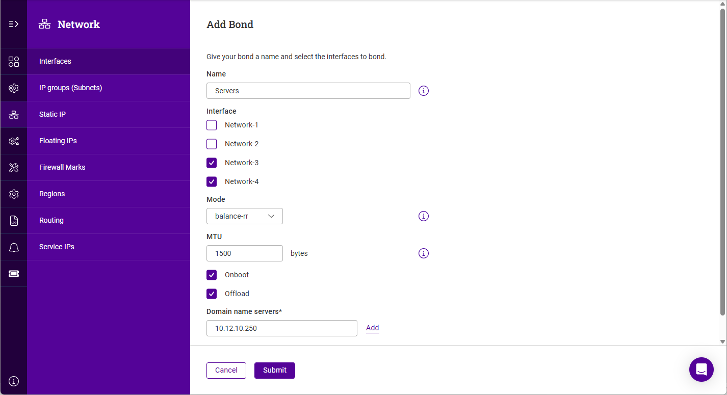
Click Add Bond.
-
Specify a Name for the bond.
-
Select the interaces to be bonded.
-
Select the bonding Mode, the options are:
-
Balance-rr - balance round robin. Transmits packets in a numerical order from the first available Secondary through to the last.
-
active-backup - This places one of the adapters in a backup state and will only become active if the link is lost to the active adapter. This mode provides fault tolerance.
-
802.3ad - Dynamic link aggregation mode. This mode requires a switch that supports IEEE 802.3ad.
-
-
Update the MTU if required.
-
Configure the required Domain name servers for the bond.
-
Click Submit.
| For multiple nodes in HA mode, configure bonding in the same way on each node. |
VLANs
To add a VLAN:
-
Using the WebUI, navigate to Network > Interfaces.
To view/edit an interface:
-
Click the three dots menu next to the Interface you’d like to view or edit.
-
Update the Name if required.
-
Update the MTU if required.
-
Enable (check) the Onboot checkbox to enable the interface on boot up.
-
Enable (check) the Offload checkbox to enable hardware NIC offloading (where available).
-
Configure the required Domain name servers for the interface.
-
Click Submit to save any changes.
Mode 0 - Balance round robin. Transmits packets in a numerical order from the first available Secondary through to the last. Mode 1 - Active Backup (default). This places one of the adapters in a backup state and will only become active if the link is lost to the active adapter. This mode provides fault tolerance. Mode 4 - 802.3ad. Dynamic link aggregation mode. This mode requires a switch that supports IEEE 802.3ad.
In access mode switch ports are dedicated to one VLAN. The switch handles all the tagging and de-tagging of frames - the station connected to the port does not need to be configured for the VLAN at all. In trunk mode the switch passes on the raw VLAN frames - the station connected must be configured to handle them. Trunk mode is usually used to connect two VLAN-carrying switches, or to connect a server or router to a switch.
If the load balancer is connected to an access mode switch port, no VLAN configuration is required. If the load balancer is connected to a trunk port, then all the required VLANs must be configured on the load balancer.
To configure a VLAN:
| For multiple nodes in HA mode, configure VLANs in the same way on each node. |
IP Groups (Subnets)
-
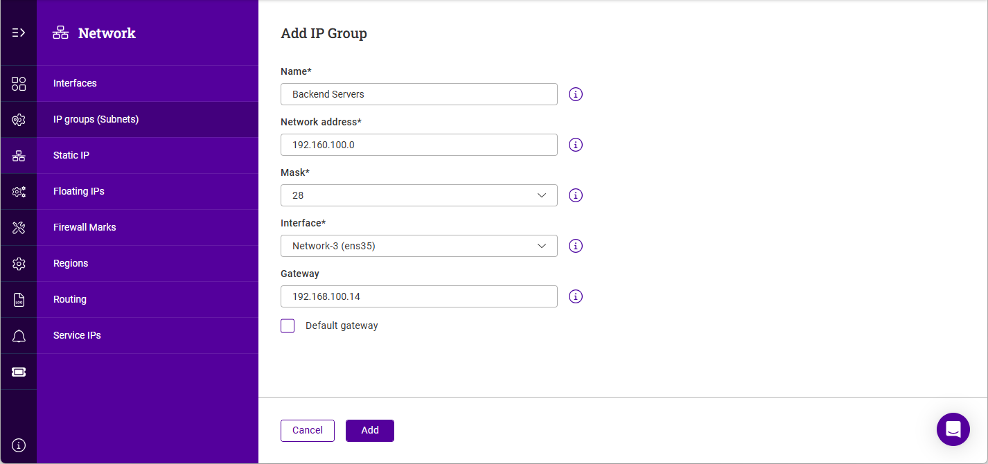
Using the WebUI, navigate to Network > Static IPs and click Add IP Group.
-
Specify a relevant Name, e.g. Backend Servers.
-
Specify the Network Address, e.g. 192.168.100.0.
-
Specify the Mask, e.g. 28.
-
Select the Interface to use for this IP group.
-
Specify the Gateway, e.g. 192.168.100.14.
-
Click Add.
| CIDR notation is used to specify the mask. For information on CIDR notation, see Appliance IPv4 Address Format (CIDR notation). |
Static IPs
Static IPs are used for:
-
The WebUI / API / SSH
-
Pulse (HA)
To add a Static IP:
-
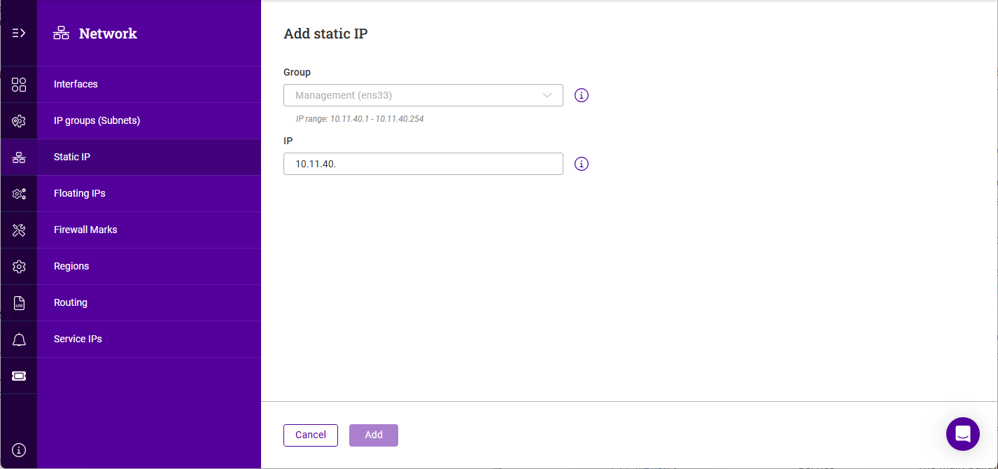
Using the WebUI, navigate to Network > Static IP and click Add static IP.
-
Select the relevant IP Group (subnet) where the IP should be created.
-
The network portion of the address with be auto filled, complete the remainder of the address.
-
Click Add.
Floating IPs
Floating IPs are used for Virtual Services. This allows the Virtual Service to move or "float" between nodes.
They are also required when using layer 4 DNAT mode or Layer 7 proxy mode with TProxy where in both cases the load balancer must be the default gateway for the Real Servers. Again, this allows the Virtual gateway to move or "float" between nodes.
Floating IPs are controlled by Pulse to ensure that only the active node owns the Floating IP(s) at any time.
To add a floating IP:
-
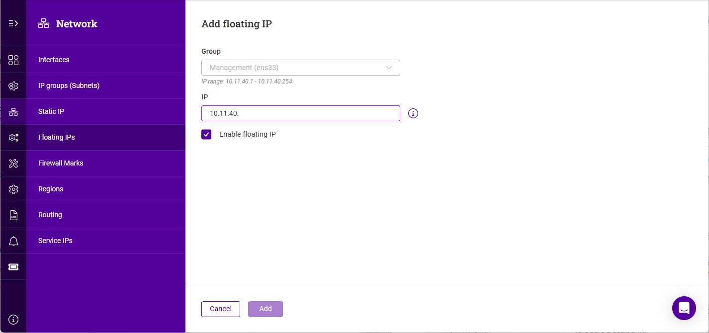
Using the WebUI, navigate to Network > Floating IPs and click Add Floating IP.
-
Select the relevant IP Group (subnet) where the IP should be created.
-
The network portion of the address with be auto filled, complete the remainder of the address.
-
By default the address will be enabled once created. If this is not desired, disable (clear) the Enable floating IP checkbox.
-
Click Add.
Firewall Marks
Firewall marks are used to group ports and protocols into a single Virtual Service. For example, firewall marks can be used to bundle HTTP connections on port 80 and secure HTTPS connections on port 443 for an e-commerce site. By assigning the same firewall mark to each protocol, state information for the transaction can be preserved because the load balancer forwards all requests from a particular client to the same Real Server.
Routing
Policy Based Routing (PBR)
If you require a custom gateway for a particular Service, this can be achieved using PBR.
| If client source addresses are known and predictable, static routes should normally be used to route traffic. In other situations where this is not known or the network is large with many subnets, PBR can be used. Here, return traffic is routed based on the source address of the reply traffic (the VIP/floating IP) rather than on the destination address (the client’s IP). |
To configure a VIP to return traffic via a custom gateway rather than via the default gateway: