Manage services
Layer 4 Services
Introduction
Layer 4 Services are based on LVS (Linux Virtual Server). LVS implements transport layer load balancing inside the Linux kernel. It is used to direct requests for TCP/UDP based services to the Real Servers and makes services on the Real Servers appear as a Virtual Service on a single IP address.
With the exception of Layer 4 SNAT mode, Layer 4 services are transparent by default, i.e. the source IP address is maintained through the load balancer to the Real Servers.
Layer 4 persistence is based on source IP and is enabled by default. The timeout is reset each time the client makes a connection, so a 5 minute persistence setting could last for hours if the client is active and regularly refreshes their connection.
Multiple ports can be specified, for example 80 & 443. In this case persistence is useful to ensure that clients hit the same backend server for both HTTP & HTTPS traffic and also to prevent the client having to renegotiate the SSL connection.
| It’s not possible to configure a Service on the same IP address as any of the network interfaces. This ensures Services can "float" (move) between nodes in HA mode. |
Adding Layer 4 Services
Layer 4 Services are configured using a template based wizard. The wizard is split into 2 stages: Frontend Configuration (the Service that clients connect to) and Backend Configuration (the pool of Real Servers that requests are distributed to).
The wizard can be run in 2 modes, selected using the drop-down at the top of the left-hand menu:
| Mode | Description |
|---|---|
Default Mode |
Displays only the most commonly used settings. Recommended for a quick, standard deployment. |
Advanced Mode |
Displays all available settings. |
| The steps below use Advanced Mode so that all available settings are described. When using Default Mode, the advanced settings are hidden and sensible defaults are applied automatically. |
To add a new Layer 4 Service:
-
Using the WebUI, navigate to Cluster Configuration > Manage Services and click Add service.
-
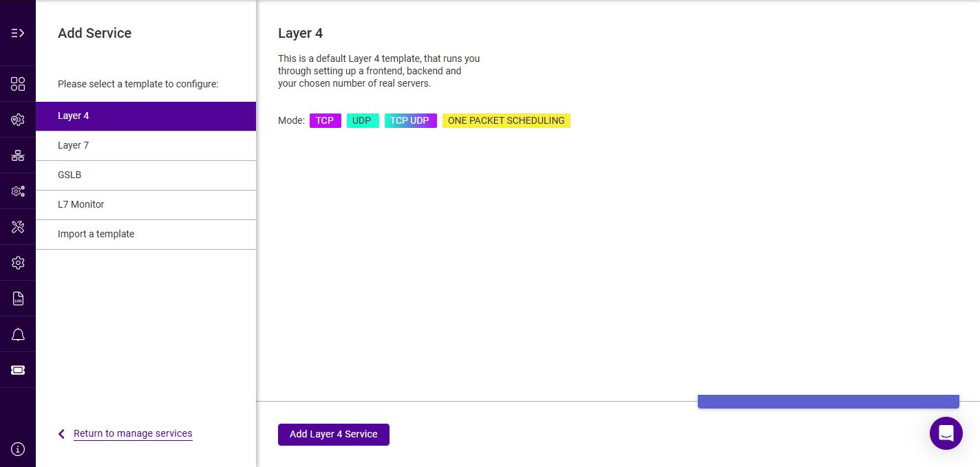
Select the Layer 4 template, then click Add Layer 4 Service.
-
To display all settings, change the mode drop-down from Default Mode to Advanced Mode.
Frontend Configuration - General
-
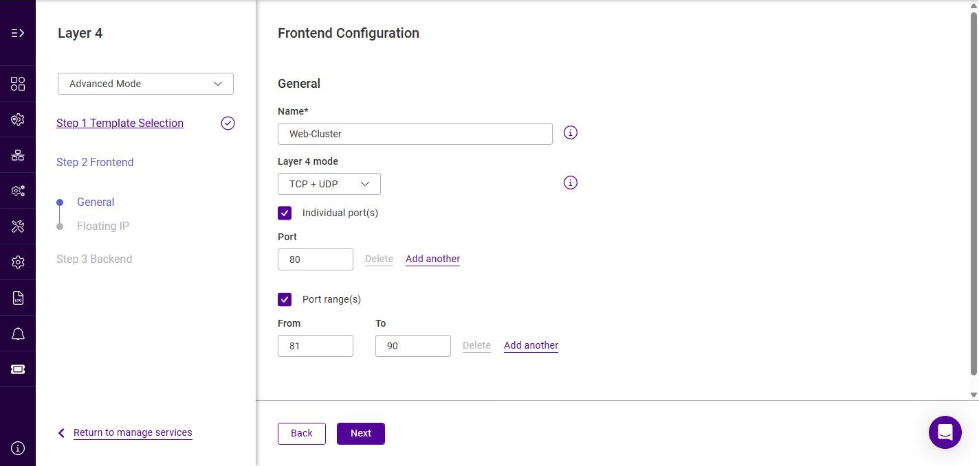
Specify a suitable Name for the service, e.g. Web-Cluster.
-
Select the required Layer 4 mode, the options are:
Layer 4 mode Description TCP + UDP
Enable both TCP and UDP. The default option.
TCP
Enable TCP only.
UDP
Enable UDP only.
One Packet Scheduling
Enable One Packet Scheduling - used for UDP SIP connections.
-
Specify the port(s) that the service should listen on:
-
Use Individual port(s) to specify one or more discrete ports. Click Add another to add additional ports.
-
Use Port range(s) to specify a contiguous range of ports (From / To). Click Add another to add additional ranges.
Multiple ports can be specified, for example 80 & 443. In this case persistence is useful to ensure that clients hit the same Real Server for both HTTP & HTTPS traffic.
-
-
Click Next.
Frontend Configuration - Floating IP
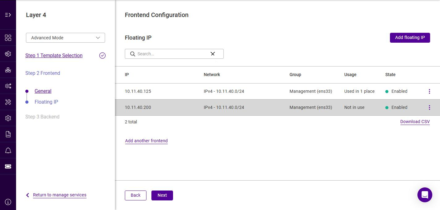
The Floating IP is the address that clients connect to. The list shows all configured Floating IPs.
-
If the required Floating IP already exists, click its row to select it (the row is highlighted when selected).
-
If the required Floating IP does not exist, click Add floating IP.
-
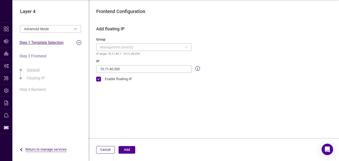
Select the Group (IP group / subnet) in which the Floating IP should be brought up. The valid IP range for the selected group is displayed below the field.
-
Specify a suitable IP address for the service, e.g. 10.11.40.200.
-
Leave Enable floating IP checked to bring the address up on the interface immediately.
-
Click Add.
For details on configuring IP groups, see IP Groups (Subnets). Floating IPs can also be managed independently - see Floating IPs.
-
-
Ensure the required Floating IP is selected, then click Next.
It’s not possible to configure a Service on the same IP address as any of the network interfaces. This ensures Services can "float" (move) between nodes in HA mode.
Backend Configuration - General
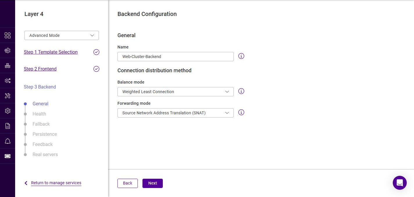
-
Optionally specify a suitable Name for the backend, e.g. Web-Cluster-Backend. If left blank a name is generated automatically.
-
Under Connection distribution method, select the required Balance mode, the options are:
Balance mode Description Weighted Least Connection
Assign more jobs to servers with fewer jobs, relative to the Real Server’s weight. The default option.
Weighted Round Robin
Assign jobs to Real Servers proportionally to the Real Server’s weight. Servers with higher weights receive new jobs first and get more jobs than servers with lower weights. Servers with equal weights receive an equal distribution of new jobs.
Destination Hash
Assign jobs to servers through looking up a statically assigned hash table by their destination IP addresses. This mode is designed for use with web proxies.
-
Select the required Forwarding mode, the options are:
Forwarding mode Description Source Network Address Translation (SNAT)
Requires no Real Server changes but is not as fast as DR mode. It is also non-transparent and therefore loses the client source IP information. The default option.
Direct Routing
Requires the "ARP Problem" to be solved on each Real Server. For more information, see DR Mode.
Destination Network Address Translation (DNAT)
Requires each Real Server to have its default gateway set as the load balancer. For more information, see NAT Mode.
Tunneling
Similar to DR mode but works across IP encapsulated tunnels.
-
Click Next.
Backend Configuration - Health
This step configures the health checks the load balancer uses to decide whether each Real Server is available. When a Real Server fails its health check it is marked down and traffic is redirected to the remaining servers; once it passes again it is automatically returned to service.
Default Mode and Advanced Mode
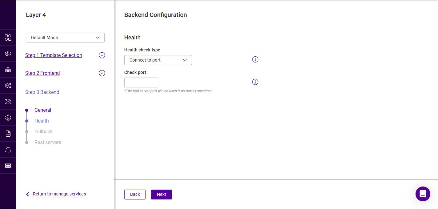
The fields shown on the Health step are the same in Default Mode and Advanced Mode - the mode (set using the selector at the top-left of the wizard) instead controls which backend steps are available. In Default Mode the backend steps are General, Health, Fallback and Real servers:
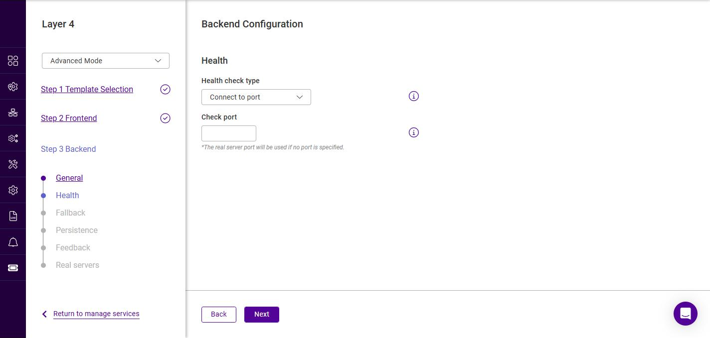
Advanced Mode adds two further backend steps - Persistence and Feedback (both described in the following sections). The Health step itself is unchanged:
Selecting the health check type
-
Select the required Health check type. When a check type is selected, the fields associated with it are displayed below.
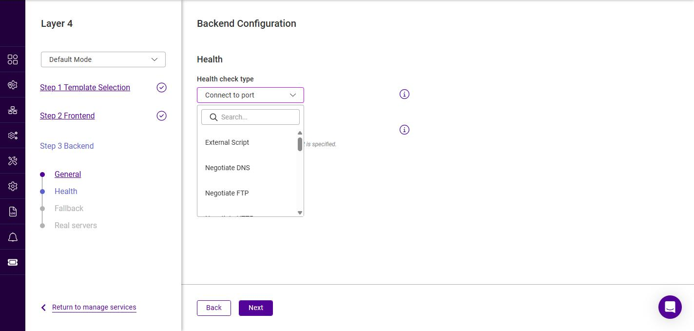
Health check type Description Connect to port
Attempts to open a TCP connection to the check port. If the connection is accepted the Real Server is considered up. A fast, protocol-agnostic check that confirms the port is open but not that the application behind it is healthy.
Negotiate HTTP
Opens an HTTP connection, requests the specified page and checks the response. The Real Server is marked up only if the expected response is returned.
Negotiate HTTP (Proxy)
As Negotiate HTTP, but performs the check via an HTTP proxy. No Host header field is used.
Negotiate HTTPS
As Negotiate HTTP, but the connection is made over SSL/TLS. Use when the Real Servers only accept encrypted connections.
Negotiate DNS
Performs a DNS check by sending a request and matching the response.
Negotiate FTP
Performs an FTP check, optionally authenticating with a username and password.
Negotiate IMAP
Performs an IMAP (mail retrieval) check, optionally authenticating with a username and password.
Negotiate IMAPS
As Negotiate IMAP, but over SSL/TLS.
Negotiate LDAP
Performs an LDAP (directory) check, optionally authenticating with a username and password.
Negotiate MySQL
Performs a MySQL database check, connecting to the named database with the supplied credentials.
Negotiate NNTP
Performs an NNTP (news) check.
Negotiate POP
Performs a POP (mail) check, optionally authenticating with a username and password.
Negotiate POPS
As Negotiate POP, but over SSL/TLS.
Negotiate RADIUS
Performs a RADIUS (authentication) check using the supplied shared secret and credentials.
Negotiate SMTP
Performs an SMTP (mail delivery) check.
External Script
Runs a custom script on the load balancer to determine Real Server health. The script must already exist on the appliance.
Ping server
Sends an ICMP echo request (ping) to the Real Server. The server is marked up if it replies.
No check, always on
Disables health checking; all Real Servers are permanently assumed to be up. Use with caution.
No check, always off
Disables health checking; all Real Servers are permanently assumed to be down.
Configuring the selected health check type
The fields that appear depend on the selected check type. The complete set of fields is described in the table below; the sections that follow show which combination of fields each check type uses.
| Setting | Description |
|---|---|
Check port |
The port to monitor. If left blank, the Real Server port is used. For multiport VIPs where the Real Server port is left blank, the first port in the list is used by default; this field overrides that. |
Host header |
For Negotiate HTTP / HTTPS only. If the Real Server requires a |
Request to send |
The file, page or command requested by the check. This can also be the name of a server-side script used to check the health of the backend application. For HTTP-based checks the default is |
Response expected |
The content that must be present in the response for the check to pass. This can be any valid regular expression; the match can be inverted by selecting Not Equals. For HTTP-based checks the default is |
Username |
For checks that authenticate (FTP, IMAP, IMAPS, LDAP, MySQL, POP, POPS, RADIUS) - the user name presented during the check. |
Password |
The password for the above user. |
Database name |
For Negotiate MySQL only. The name of the MySQL database to connect to. |
Radius secret |
For Negotiate RADIUS only. The shared secret string used to authenticate to the RADIUS server. |
External check script |
For External Script only. Selects the script used to determine Real Server health, from the scripts available on the appliance. To add new scripts, see Health checks. |
The field combinations are as follows.
Connect to port, Ping server, No check (always on / always off)
Connect to port shows only the Check port field (see the images above). Ping server, No check, always on and No check, always off have no additional fields.
Negotiate HTTP / HTTPS
These checks show Check port, Host header, Request to send and Response expected:
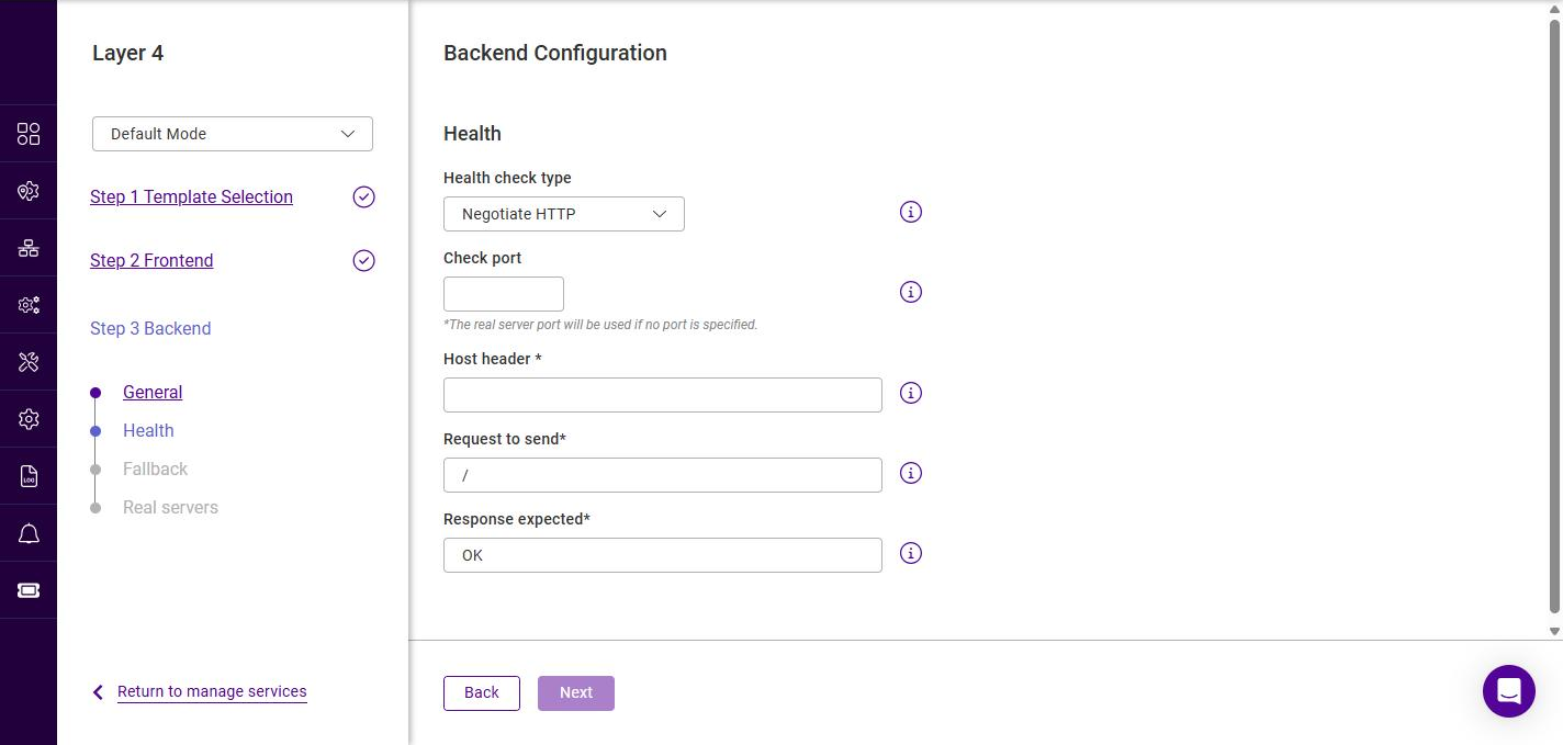
| Negotiate HTTP (Proxy) shows the same fields except Host header. |
Negotiate DNS
Shows Check port, Request to send and Response expected.
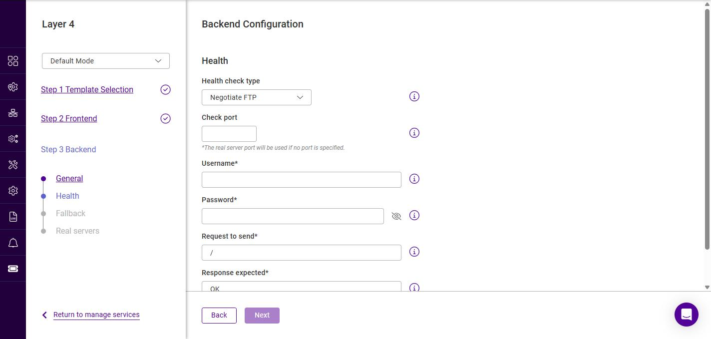
Negotiate FTP
Shows Check port, Username, Password, Request to send and Response expected:
Negotiate IMAP / IMAPS / LDAP / POP / POPS
These checks show Check port, Username and Password.
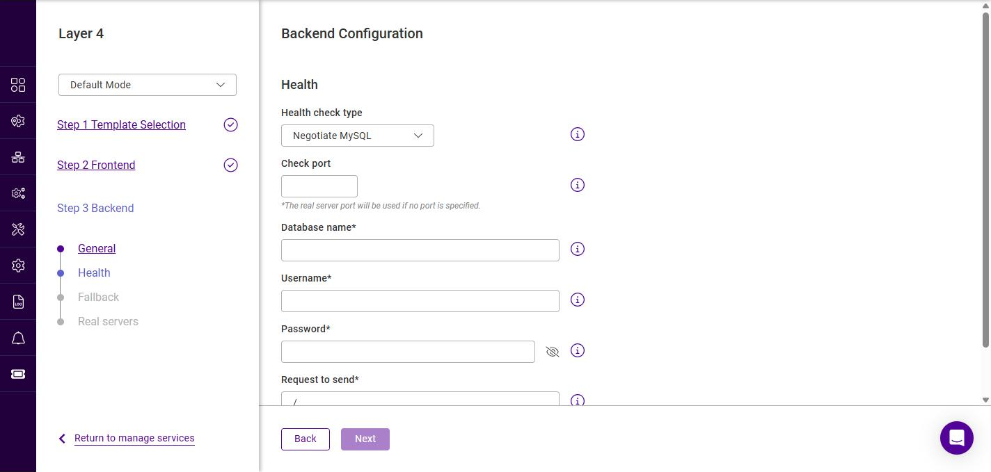
Negotiate MySQL
Shows Check port, Database name, Username, Password and Request to send:
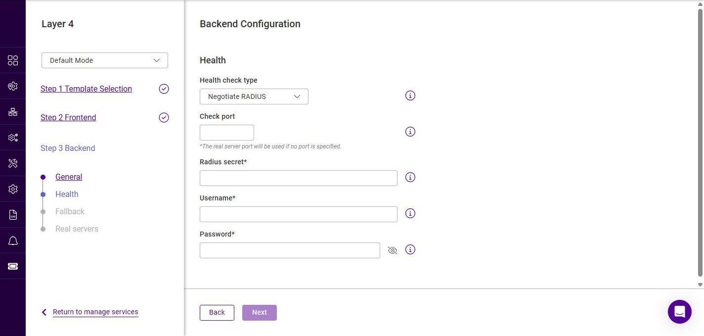
Negotiate RADIUS
Shows Check port, Radius secret, Username and Password:
Negotiate NNTP / SMTP
These checks show only the Check port field.
External Script
Shows Check port and External check script:
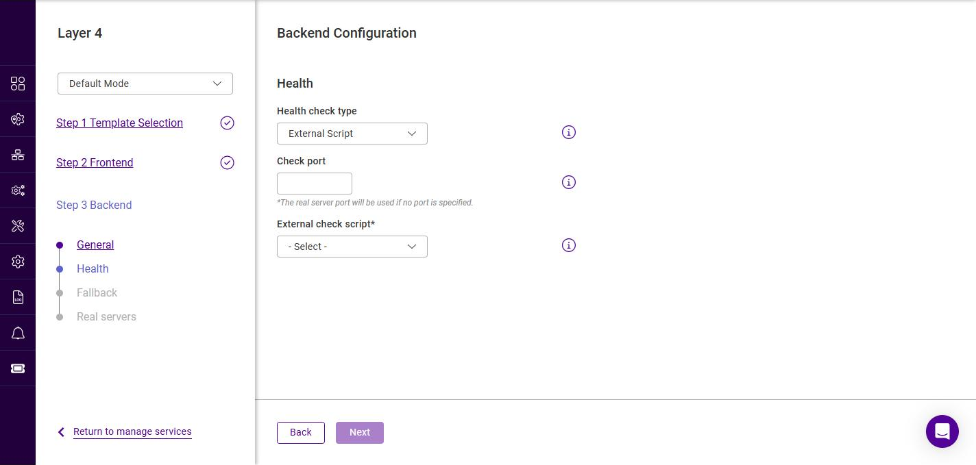
Once the health check has been configured, click Next.
Backend Configuration - Fallback
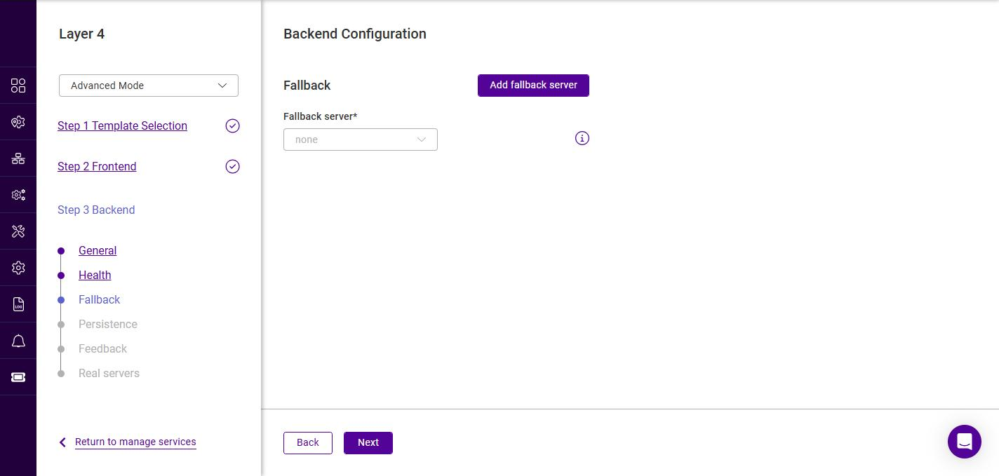
The fallback server is presented to clients when all Real Servers in the backend are down. This step is optional - to skip it, leave the Fallback server set to none and click Next.
-
If the required fallback server already exists, select it in the Fallback server list.
-
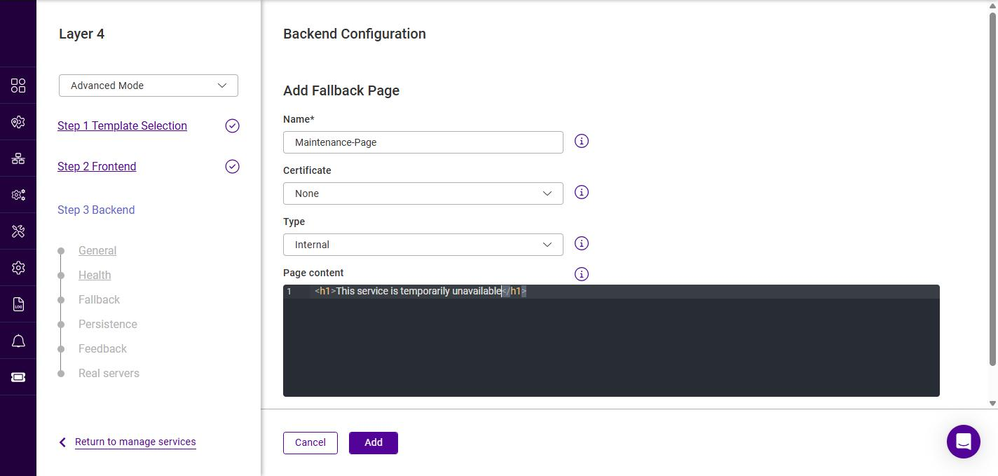
If the fallback server does not exist, click Add fallback server.
-
Specify a suitable Name.
-
Select a Certificate if the page should be served over HTTPS.
-
Select the Type:
-
If Internal is selected, enter the Page content (HTML) to serve in the editor.
-
If External is selected, specify the IP address and Port of the external fallback server.
-
-
Click Add.
-
-
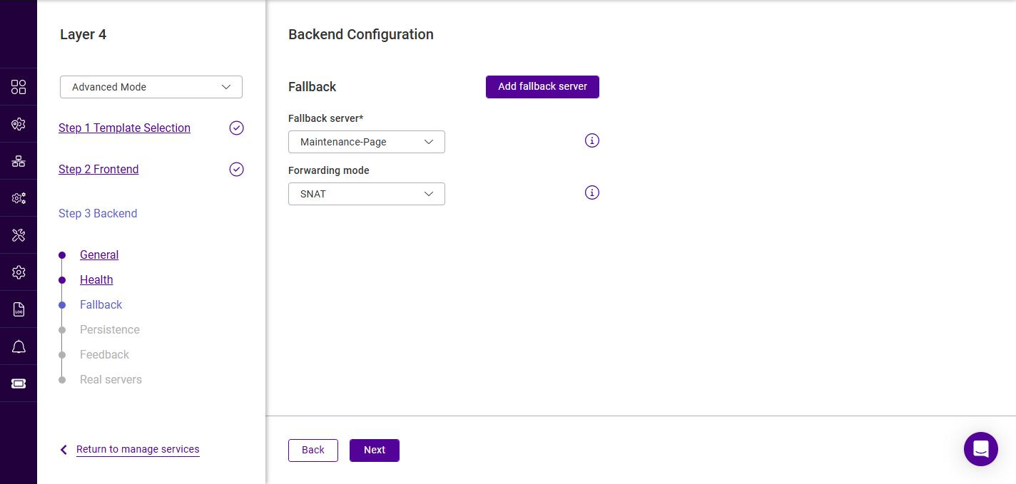
Once a fallback server is selected, a Forwarding mode field is displayed.
-
Select the required Forwarding mode for the fallback server. The options are the same as for the backend - SNAT (default), Direct Routing, DNAT and Tunneling (see the Forwarding mode table above).
-
Click Next.
Backend Configuration - Persistence
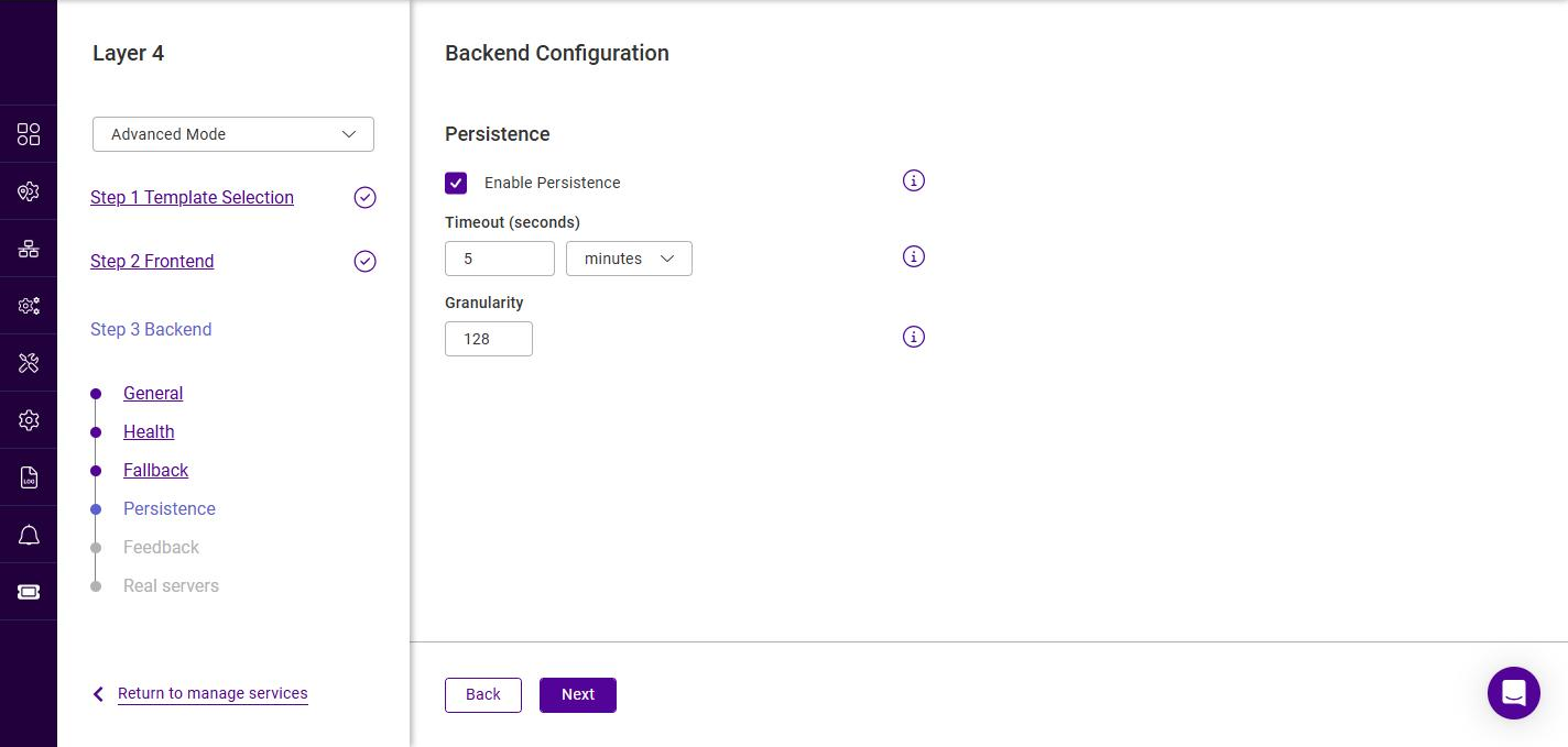
Layer 4 persistence is based on the client source IP address.
-
Use the Enable Persistence checkbox to enable or disable persistence (enabled by default). Persistent connections are required for some protocols such as FTP and SIP, are beneficial when using SSL to avoid re-negotiation, and can be required with HTTP if your web application cannot keep state between Real Servers.
-
If enabled, set the required Timeout. Enter a value and select the unit (seconds, minutes, hours or days); the default is 5 minutes. The timeout is reset on every new client connection.
-
If enabled, set the Granularity. The granularity level sets how many clients are grouped to a single Real Server. The default mask is 255.255.255.255 (or 128 for IPv6), meaning persistence is per individual client host. Less specific masks such as 255.255.255.0 (or /24 for IPv6) can be used to direct all clients within a network to the same Real Server.
-
Click Next.
Backend Configuration - Feedback
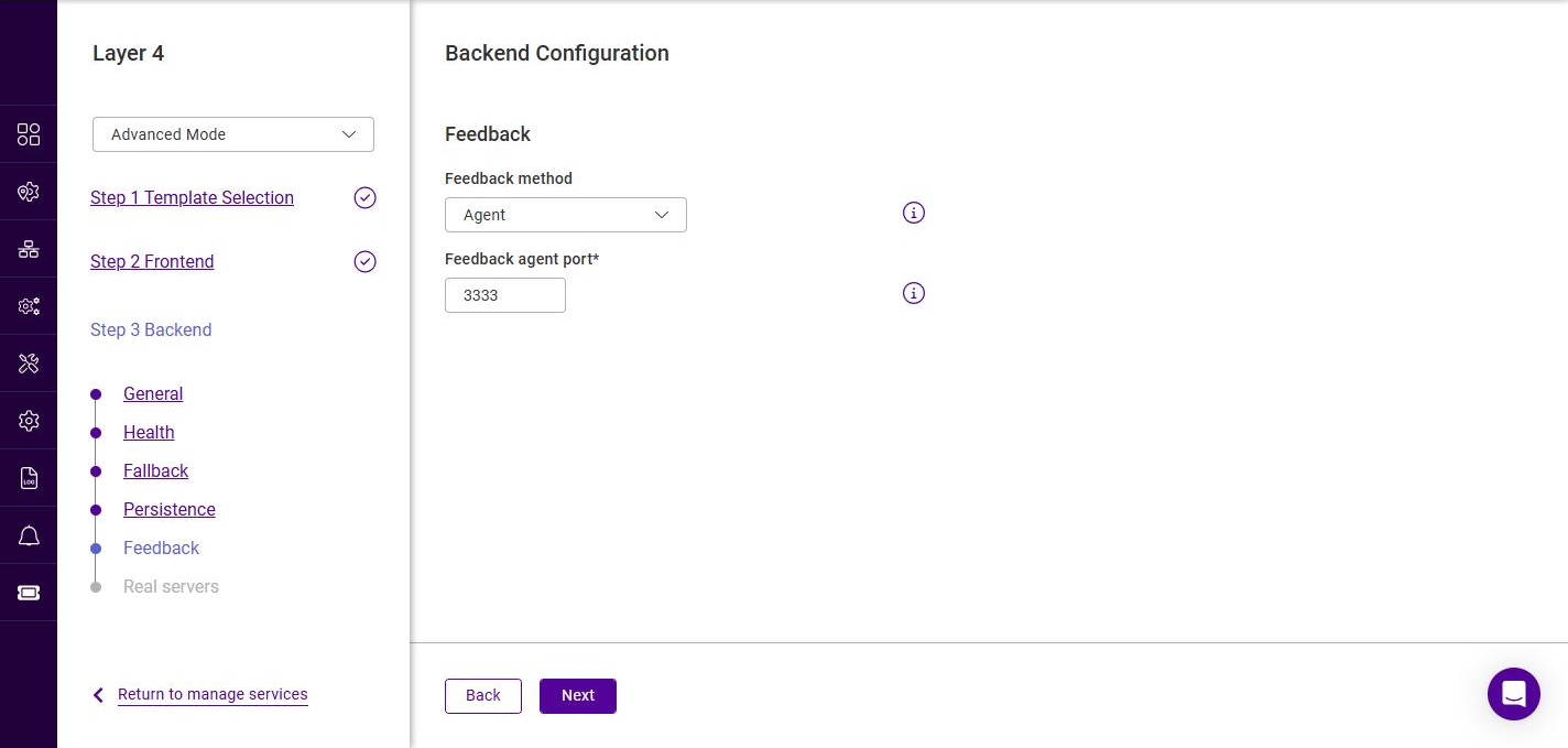
The feedback method allows the load balancer to adjust the weighting of each Real Server based on its real-time load.
-
Select the required Feedback method, the options are:
Feedback method Description None
No feedback is used. The default option.
Agent
Use runtime data from the feedback agent installed on each Real Server. Specify the Feedback agent port (the default is 3333). For details on the feedback agent, see Server Feedback Agent.
HTTP
Use any HTTP server responding on the feedback agent port (default 3333) to provide feedback information to the load balancer.
-
Click Next.
Backend Configuration - Real servers
-
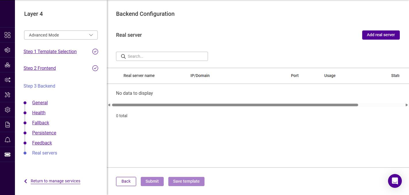
Click Add real server.
-
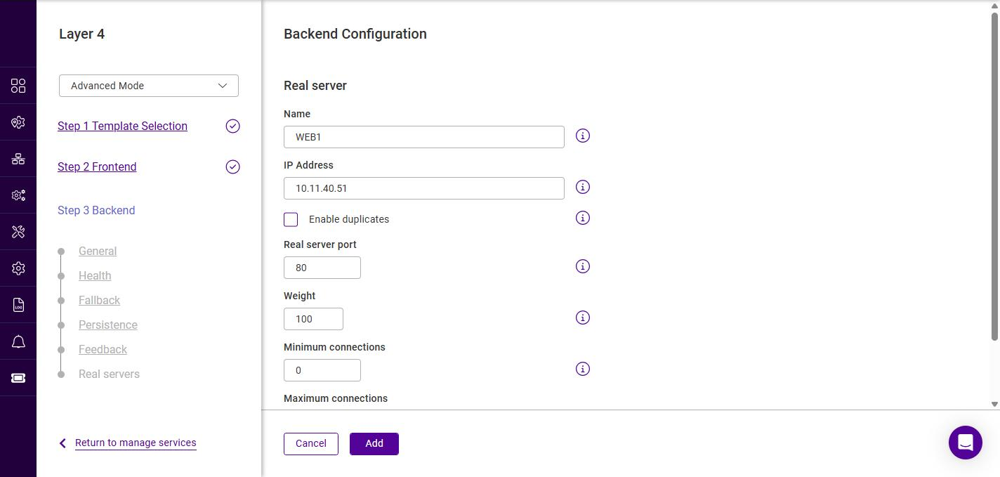
Configure the Real Server:
Setting Description Name
A suitable name for the Real Server, e.g. WEB1.
IP Address
The IP address of the Real Server.
Enable duplicates
Allows the same IP address to be added more than once, for example on different ports.
Real server port
The port the Real Server listens on. If left blank, the port specified for the frontend is used.
Weight
An integer specifying the capacity of the server relative to the others in the pool. Valid values are 0 to 65535, the default is 100. The higher the value, the more connections the server receives. A weight of 0 places the server in drain mode.
Minimum connections
The lower connection threshold of the server. Valid values are 0 to 65535. The default is 0, which means the threshold is not set. If set, the server receives new connections when its connection count drops below this threshold.
Maximum connections
The upper connection threshold of the server. Valid values are 0 to 65535. The default is 0, which means the threshold is not set.
-
Click Add, then repeat to add additional Real Servers.
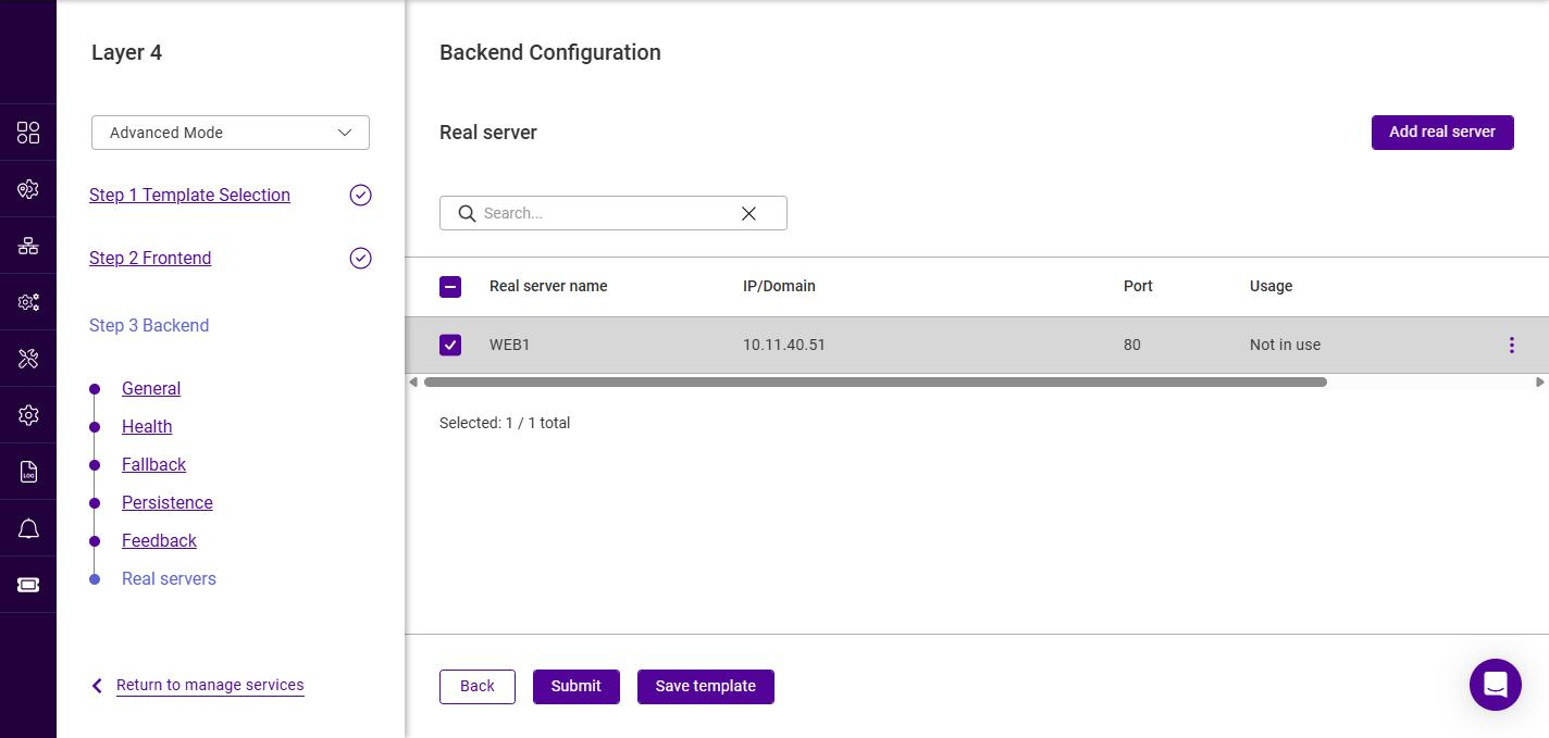
-
Ensure the required Real Servers are selected (checked).
Submitting the Service
-
Once all Real Servers have been added, click Submit to create the service.
The new Layer 4 Service is now listed under Manage Services with a Status of Pending until the firewall and load balancing services are updated.
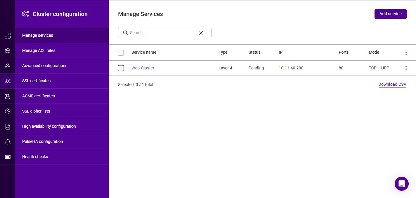
|
To activate the new service, the underlying services must be updated:
|
Duplicating Layer 4 Services
If you have existing Layer 4 Services, these can be duplicated. During the duplication process, the name and the IP address and/or port must be changed so that it does not clash with the source Service.
To duplicate an existing layer 4 Service:
-
Click the three dots menu next to the Service you’d like to duplicate.
-
Click Duplicate.
-
Update the Name for the new Service.
-
Update the Port if required.
-
Click Next.
-
Update the Floating IP address if required.
At least one of these settings must be changed to ensure that the service can be created. -
Click Update.
Modifying Layer 4 Services
Frontend
-
Navigate to Cluster Configuration > Manage services.
-
Click the three dots menu next to the service to be modified and select Edit.
-
Select the section to be modified in the area to the left. Make the changes required, click Next to step through the remaining sections, then click Submit to save the changes.
DR Mode Considerations
The ARP Problem
DR mode works by changing the MAC address of the inbound packets to match the Real Server selected by the load balancing algorithm. To enable DR mode to operate:
-
The load balanced application/service/daemon running on each Real Server must be able to accept traffic destined for the VIP address and the Real Server’s own IP address (RIP). This is because in DR mode the destination address of load balanced packets is the VIP address, whilst for other traffic such as health checks, administration traffic etc. it’s the Real Server’s own IP address (the RIP).
-
Each Real Server must be configured so that it does not respond to ARP requests for the VIP address - only the load balancer should do this.
Configuring the Real Servers in this way is known as "Solving the ARP Problem". The steps required depend on the particular operating system being used.
Solving the ARP Problem for Linux
There are two different approaches on how to configure a Linux server for correct operation when DR mode load balancing is in use:
-
Modifying the server’s ARP behavior and adding the relevant VIP addresses to the loopback interface
-
Using NAT to convince the server to accept and reply to packets addressed to the relevant VIP addresses
Four independent methods are described below along with instructions. Each method follows one of the two approaches above. The specific method chosen will depend on technical requirements, the Linux distribution in use, and personal preferences.
The first method involves setting kernel parameters to alter the server’s ARP behavior and adding IP addresses to the loopback interface. This method should be universally applicable to any Linux server making this the preferred method.
If setting kernel parameters and adding IP addresses is not possible for some reason, the remaining three methods describe setting up a server for DR mode operation by using NAT via the redirect target/statement. The specific instructions depend on the packet filtering framework and tooling in use, which varies between Linux distributions. Methods are presented for iptables, nftables, and the firewall-cmd tool.
Method 1: ARP Behavior and Loopback Interface Changes
This is the preferred method as it should be applicable to any Linux server and doesn’t require any additional packet filtering or NAT considerations.
Each real server needs the loopback interface to be configured with the virtual IP addresses (VIPs) of the relevant load balanced services. This is often just a single VIP address, but the logic described below can be extended to cover multiple VIPs on a server. Having the VIPs on the loopback interface allows the server to accept inbound load balanced packets that are addressed to a VIP.
The server must not respond to ARP requests for the VIP addresses. The server also must not use ARP to announce the fact that it owns the VIP addresses. This is necessary to prevent IP address conflicts, as all of the real servers and the load balancer will own the VIP addresses. Only the load balancer should announce ownership of the VIPs.
To configure the behavior described above, follow all of the steps below on each real server.
Step 1 of 4: Re-configuring ARP behavior
This step is only applicable if IPv4-based virtual services are in use.
Add the following lines to the file /etc/sysctl.conf (create this file if it does not already exist):
net.ipv4.conf.all.arp_ignore=1
net.ipv4.conf.eth0.arp_ignore=1
net.ipv4.conf.eth1.arp_ignore=1
net.ipv4.conf.all.arp_announce=2
net.ipv4.conf.eth0.arp_announce=2
net.ipv4.conf.eth1.arp_announce=2
Adjust the commands shown above to suit the server’s network configuration, e.g. a different number of network interfaces or a different interface naming convention.
For Linux distros such as Debian 12+, Ubuntu 24.10+ and OpenSUSE that are using systemd and are running systemd-sysctl, /usr/lib/sysctl.d/50-default.conf should be modified rather than /etc/sysctl.conf.
|
|
For reference, the effect of these kernel parameter changes on the server is as follows:
|
Step 2 of 4: Re-configuring duplicate address detection (DAD) behavior
This step is only applicable if IPv6-based virtual services are in use.
Add the following lines to the file /etc/sysctl.conf (create this file if it does not already exist):
net.ipv6.conf.lo.dad_transmits=0
net.ipv6.conf.lo.accept_dad=0
For Linux distros such as Debian 12+, Ubuntu 24.10+ and OpenSUSE that are using systemd and are running systemd-sysctl, /usr/lib/sysctl.d/50-default.conf should be modified rather than /etc/sysctl.conf.
|
|
For reference, the effect of these kernel parameter changes on the server is as follows:
|
Step 3 of 4: Applying the new settings
To apply the new settings, either reboot the real server or execute the following command to immediately apply the changes:
/sbin/sysctl -p
|
Steps 1, 2, and 3 can be replaced by instead modifying the necessary kernel variables by writing directly to their corresponding files under Execute the following commands (as root) to implement these temporary changes (adapting the number of interfaces and interface names as needed): echo 1 > /proc/sys/net/ipv4/conf/all/arp_ignore echo 1 > /proc/sys/net/ipv4/conf/eth0/arp_ignore echo 1 > /proc/sys/net/ipv4/conf/eth1/arp_ignore echo 2 > /proc/sys/net/ipv4/conf/all/arp_announce echo 2 > /proc/sys/net/ipv4/conf/eth0/arp_announce echo 2 > /proc/sys/net/ipv4/conf/eth1/arp_announce echo 0 > /proc/sys/net/ipv6/conf/lo/dad_transmits echo 0 > /proc/sys/net/ipv6/conf/lo/accept_dad |
Step 4 of 4: Adding the virtual IP addresses (VIPs) to the loopback interface
Each of the VIP addresses must be permanently added to the loopback interface. VIPs must be added with a network prefix of /32 for IPv4 addresses or /128 for IPv6 addresses. The IP addresses can be added using the usual configuration files and tools for modifying network interfaces, which vary between different Linux distributions.
As an alternative, the ip command can be used as a universal way to add IP addresses to any Linux server. Note that addresses added in this way will not persist across reboots. To make these addresses permanent, add the ip commands to an appropriate startup script such as /etc/rc.local.
Execute the following ip command for each IPv4 VIP:
ip addr add dev lo <IPv4-VIP>/32
Execute the following ip command for each IPv6 VIP:
ip addr add dev lo <IPv6-VIP>/128
To check that the VIPs have been successfully added, execute the command:
ip addr ls
To remove an IPv4 VIP from the loopback adapter, execute the command:
ip addr del dev lo <IPv4-VIP>/32
To remove an IPv6 VIP from the loopback adapter, execute the command:
ip addr del dev lo <IPv6-VIP>/128
Method 2: NAT "redirect" via iptables
iptables can be used on each real server to identify incoming packets that are addressed to a virtual IP address (VIP) and redirect those packets to the server itself. This is achieved using the REDIRECT target in iptables, which performs the necessary NAT to make this possible. This allows a real server to accept packets addressed to a VIP without the server owning the VIP.
Execute the following command to put the necessary iptables rule in place to redirect traffic for a single IPv4 VIP address. Note that iptables rules added in this way will not persist across reboots. To make such a rule permanent, either add the rule to an iptables firewall script, if one is provided with the Linux distribution in question, or add the command to an appropriate startup script such as /etc/rc.local on each real server.
iptables -t nat -A PREROUTING -d <IPv4-VIP> -j REDIRECT
The VIP address should be changed to match the virtual service in question, for example:
iptables -t nat -A PREROUTING -d 10.0.0.21 -j REDIRECT
The example above will redirect any incoming packets destined for 10.0.0.21 (the virtual service) locally, i.e. to the primary address of the incoming interface on the real server.
If a real server is responsible for serving multiple VIPs then additional iptables rules should be added to cover each VIP.
For an IPv6 VIP address, a command like the following should be used:
ip6tables -t nat -A PREROUTING -d <IPv6-VIP> -j REDIRECT
The VIP address should be changed to match the virtual service in question, for example:
ip6tables -t nat -A PREROUTING -d 2001:db8::10 -j REDIRECT
| Method 2 may not be appropriate when using IP-based virtual hosting on a web server. This is because an iptables REDIRECT rule will redirect incoming packets to the primary address of the incoming interface on the web server rather than any of the virtual hosts that are configured. Where this is an issue, use method 1 instead. |
Method 3: NAT "redirect" via nftables
nftables is the modern Linux kernel packet filtering framework. It is supported on all major Linux distributions and has replaced iptables as the default framework on most major distributions.
nftables can be used on each real server to identify incoming packets that are addressed to a virtual IP address (VIP) and redirect those packets to the server itself. This is achieved using the redirect statement in nftables, which performs the necessary NAT to make this possible. This allows a real server to accept packets addressed to a VIP without the server owning the VIP.
Use a script like the following to put the necessary nftables structures in place to redirect traffic for both IPv4 and IPv6 VIP addresses. To make such a configuration permanent, either add the inet nat table to an nftables firewall script, if one is provided with the Linux distribution in question, or configure a script like the following to execute as a startup script on each real server.
#!/usr/sbin/nft -f

table inet nat {
    chain prerouting {
        comment "Allow server to accept packets destined for VIP addresses";
        type nat hook prerouting priority -100; policy accept;
        ip daddr <IPv4-VIP> redirect comment "Description"
        ip6 daddr <IPv6-VIP> redirect comment "Description"
    }
}
The VIP addresses and comments should be changed to match the virtual services in question, for example:
#!/usr/sbin/nft -f

table inet nat {
    chain prerouting {
        comment "Allow server to accept packets destined for VIP addresses";
        type nat hook prerouting priority -100; policy accept;
        ip daddr 10.0.0.21 redirect comment "VIP 1: HTTP"
        ip6 daddr 2001:db8::10 redirect comment "VIP 2: HTTPS"
    }
}
The example above will redirect any incoming packets destined for 10.0.0.21 or 2001:db8::10 (the virtual services) locally, i.e. to the primary address of the incoming interface (for each IP version) on the real server.
Note that Linux kernels prior to 5.2 may not support performing NAT (which is required for the redirect statement) in an inet family table. In this scenario, use either an ip or an ip6 family table instead, or both if a mixture of IPv4 and IPv6 VIPs are in use on the same server. Also note that older kernels may not support the use of comments in chains.
Note that Linux kernels prior to 4.18 require explicitly registering both prerouting and postrouting chains in order for the implicit NAT of the redirect statement to be correctly performed in both the inbound and outbound directions.
A legacy-friendly setup may look like the following:
#!/usr/sbin/nft -f

table ip nat {
    chain prerouting {
        type nat hook prerouting priority -100; policy accept;
        ip daddr 10.0.0.21 counter redirect comment "VIP 1: HTTP"
    }

    chain postrouting {
        type nat hook postrouting priority 100; policy accept;
    }
}

table ip6 nat {
    chain prerouting {
        type nat hook prerouting priority -100; policy accept;
        ip6 daddr 2001:db8::10 counter redirect comment "VIP 2: HTTPS"
    }

    chain postrouting {
        type nat hook postrouting priority 100; policy accept;
    }
}
| Method 3 may not be appropriate when using IP-based virtual hosting on a web server. This is because an nftables redirect statement will redirect incoming packets to the primary address of the incoming interface on the web server rather than any of the virtual hosts that are configured. Where this is an issue, use method 1 instead. |
Method 4: NAT "redirect" via firewall-cmd
Some recent versions of Linux distributions make use of firewalld as a high-level firewall configuration framework. In this case, while it may actually be iptables performing the work at a lower level, it may be preferred to implement the iptables NAT solution described in method 2 in firewalld, as opposed to directly manipulating iptables. This is achieved by using the firewall-cmd tool provided by firewalld and executing a command like the following on each real server:
firewall-cmd --permanent --direct --add-rule ipv4 nat PREROUTING 0 -d <IPv4-VIP> -j REDIRECT
The VIP address should be changed to match the virtual service in question, for example:
firewall-cmd --permanent --direct --add-rule ipv4 nat PREROUTING 0 -d 10.0.0.50 -j REDIRECT
To apply the new configuration, reload the firewall rules like so:
firewall-cmd --reload
Configuration applied in this way will be permanent and will persist across reboots.
| Method 4 may not be appropriate when using IP-based virtual hosting on a web server. This is because an iptables REDIRECT rule will redirect incoming packets to the primary address of the incoming interface on the web server rather than any of the virtual hosts that are configured. Where this is an issue, use method 1 instead. |
Solving the ARP Problem for Solaris
For Solaris v11 and later, run the following command on each Real Server:
ipadm create-addr -a <VIP>/32 lo0
The configuration survives a reboot so there’s no need to add this command to a startup script.
Solving the ARP Problem for Mac OS X/BSD
OS X is BSDish, so you need to use BSDish syntax:
ifconfig lo0 alias <VIP> netmask 255.255.255.255 -arp up
You’ll need to add this to the startup scripts on all of your Real Servers.
| Don’t forget that the service on the Real Servers needs to listen on both the RIP address and VIP address as mentioned previously. |
| Failure to correctly configure the Real Servers to handle the "ARP Problem" is the most common issue when using DR mode. |
Solving the ARP Problem for Windows Servers
Windows Server 2012 & Later
Windows Server 2012 and later support Direct Routing (DR) mode through the use of the Microsoft Loopback Adapter that must be installed and configured on each load balanced (Real) Server. The IP address configured on the Loopback Adapter must be the same as the Virtual Service (VIP) address. This enables the server to receive packets that have their destination set as the VIP address. If a Real Server is included in multiple DR mode VIPs, an IP address for each VIP must be added to the Loopback Adapter.
In addition, the strong/weak host behavior must be configured on each Real Server. The weak host model allows packets with any IP to be sent or received via an interface. The strong host model only allows packets with an IP belonging to the interface to be sent or received.
| The following 3 steps must be completed on all Real Servers associated with the VIP. |
Step 1 of 3: Install the Microsoft Loopback Adapter
-
Click Start, then run hdwwiz to start the Hardware Installation Wizard.
-
Once the Wizard has started, click Next.
-
Select Install the hardware that I manually select from a list (Advanced), click Next.
-
Select Network adapters, click Next.
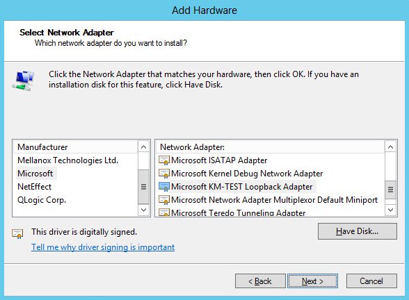
-
Select Microsoft & Microsoft KM-Test Loopback Adapter, click Next.
-
Click Next to start the installation, when complete click Finish.
Step 2 of 3: Configure the Loopback Adapter
-
Open Control Panel and click Network and Sharing Center.
-
Click Change adapter settings.
-
Right-click the new Loopback Adapter and select Properties.
| You can configure IPv4 or IPv6 addresses or both depending on your requirements. |
IPv4 Addresses
-
Uncheck all items except Internet Protocol Version 4 (TCP/IPv4) as shown below:
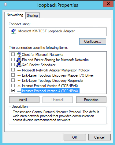
-
Ensure that Internet Protocol Version (TCP/IPv4) is selected, click Properties and configure the IP address to be the same as the Virtual Service address (VIP) with a subnet mask of 255.255.255.255, e.g. 192.168.2.20/255.255.255.255 as shown below:
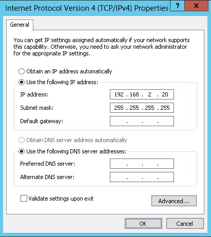
192.168.2.20 is an example, make sure you specify the correct VIP address. If a Real Server is included in multiple DR mode VIPs, an IP address for each VIP must be added to the Loopback Adapter. -
Click OK then click Close to save and apply the new settings.
IPv6 Addresses
-
Uncheck all items except Internet Protocol Version 6 (TCP/IPv6) as shown below:
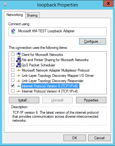
-
Ensure that Internet Protocol Version (TCP/IPv6) is selected, click Properties and configure the IP address to be the same as the Virtual Service (VIP) and set the Subnet Prefix Length to be the same as your network setting, e.g. 2001:470:1f09:e72::15/64 as shown below:
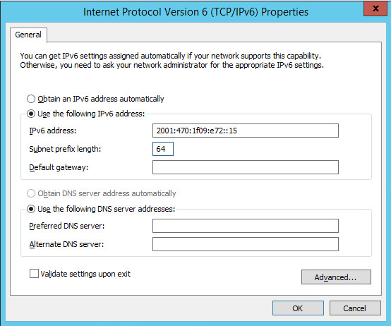
2001:470:1f09:e72::15/64 is an example, make sure you specify the correct VIP address. If a Real Server is included in multiple DR mode VIPs, an IP address for each VIP must be added to the Loopback Adapter. -
Click OK then click Close to save and apply the new settings.
Step 3 of 3: Configure the strong/weak host behavior
The strong/weak host behavior can be configured using either of the following 2 methods:
-
Option 1 - Using network shell (netsh) commands
-
Option 2 - Using PowerShell cmdlets
The commands in this section assume that the LAN Adapter is named "net" and the Loopback Adapter is named "loopback" as shown in the example below:
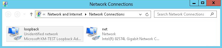
|
Either adjust the commands to use the names allocated to your LAN and loopback adapters, or rename the adapters before running the commands. Names are case sensitive so make sure that the interface names used in the commands match the adapter names exactly. |
Option 1 - Using Network Shell (netsh) Commands
To configure the correct strong/weak host behavior run the following commands:
For IPv4 addresses:
netsh interface ipv4 set interface "net" weakhostreceive=enabled
netsh interface ipv4 set interface "loopback" weakhostreceive=enabled
netsh interface ipv4 set interface "loopback" weakhostsend=enabled
For IPv6 addresses:
netsh interface ipv6 set interface "net" weakhostreceive=enabled
netsh interface ipv6 set interface "loopback" weakhostreceive=enabled
netsh interface ipv6 set interface "loopback" weakhostsend=enabled
netsh interface ipv6 set interface "loopback" dadtransmits=0
Option 2 - Using PowerShell Cmdlets
For IPv4 addresses:
Set-NetIpInterface -InterfaceAlias loopback -WeakHostReceive enabled -WeakHostSend enabled -AddressFamily IPv4
Set-NetIpInterface -InterfaceAlias net -WeakHostReceive enabled -AddressFamily IPv4
For IPv6 Addresses:
Set-NetIpInterface -InterfaceAlias loopback -WeakHostReceive enabled -WeakHostSend enabled -DadTransmits 0 -AddressFamily IPv6
Set-NetIpInterface -InterfaceAlias net -WeakHostReceive enabled -AddressFamily IPv6
Verify the Strong/Weak Host Configuration
The following PowerShell Cmdlets can be used to verify the settings:
The "net" interface:
netsh interface ipv4 show interface net
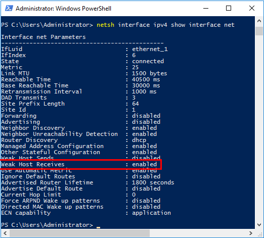
The "loopback" interface:
netsh interface ipv4 show interface loopback
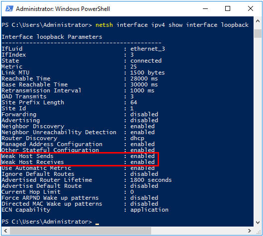
| For IPv6, replace "ipv4" with "ipv6" in the above commands. |
For Windows 2012 & later you can also use the following PowerShell Cmdlets to verify the settings:
To view both IPv4 and IPv6:
Get-NetIpInterface -InterfaceAlias loopback | FL
for IPv4 only:
Get-NetIpInterface -InterfaceAlias loopback -AddressFamily IPv4 | FL
for IPv6 only:
Get-NetIpInterface -InterfaceAlias loopback -AddressFamily IPv6 | FL
| Failure to correctly configure the Real Servers to handle the "ARP Problem" is the most common issue when using DR mode. |
Solving the ARP Problem - Possible Side Effect for Windows 2012 & Later
With DR Mode, the source IP address of return traffic from a Real Server will be the IP address assigned to the loopback adapter, which is the same as the VIP address that the client connected to. For traffic initiated by a Real Server, the source IP address should under normal circumstances be the Real Server’s own IP address, i.e. the address assigned to the standard network adapter.
However, due to the way the network adapters are configured to solve the "ARP Problem", and the way that Windows selects the source IP address, it’s possible under certain circumstances for the source IP address of traffic initiated by a Real Server to be the IP address configured on the loopback adapter rather than the Real Server’s own IP address. Please refer to this Microsoft article for more information on how Windows selects the source IP address.
To prevent the IP address(es) assigned to the loopback adapter being used in this way, the skipassource flag must be set for each IP assigned to the loopback adapter.
To check the current skipassource setting for all IPs associated with the loopback adapter, use the following command:
Get-NetAdapter -name loopback | Get-NetIPAddress | select ipaddress, skipassource
-
If your loopback adapter is not named "loopback" modify the command accordingly
Example output:
ipaddress       skipassource
---------       ------------
192.168.111.180        false
This shows that for the 192.168.111.180 address, the skipassource flag is not set.
To set the skipassource flag for the 192.168.111.180 address, use the following command:
Set-NetIPAddress –IPAddress 192.168.111.180 –SkipAsSource $True
To clear the skipassource flag for the 192.168.111.180 address, use the following command:
Set-NetIPAddress –IPAddress 192.168.111.180 –SkipAsSource $False
To set the skipassource flag for all IP addresses associated with the loopback adapter, the following two PowerShell commands can be used:
[array]$IPs = Get-NetIPAddress -InterfaceAlias loopback
Set-NetIPAddress -IPAddress $IPs.IPAddress -InterfaceAlias loopback -SkipAsSource $true
-
The first command gathers all IP addresses assigned to the loopback adapter
-
The second command then sets the SkipAsSource flag for all IPs found
-
If your loopback adapter is not named "loopback" modify the commands accordingly
| Make the sure that the same settings are configured on all Real Servers. |
Other Windows Settings that May Cause Issues
Receive Segment Coalescing (RSC)
RSC is a stateless offload technology that helps reduce CPU utilization for network processing on the receive side by offloading tasks from the CPU to an RSC-capable network adapter. In rare cases it has been discovered that RSC can adversely effect performance when using DR mode. In these cases the performance issue was addressed by disabling RSC.
To check the current RSC settings for all RSC compatible interfaces, use the following command:
Get-NetAdapterRsc
Example output:
Name  IPv4Enabled  IPv6Enabled  IPv4Operational IPv6Operational IPv4FailureReason IPv6FailureReason
                                State           State
----  -----------  -----------  --------------- --------------- ----------------- -----------------
net   True         True         True            True            NoFailure         NoFailure
-
In this example IPv4Operational State and IPv6Operational State are set to True which shows that RSC is enabled for both IPv4 and IPv6
RSC can be disabled and enabled using the GUI or by using PowerShell commands.
Using the GUI
RSC for IPv4 (Recv Segment Coalescing (IPv4)) and for IPv6 (Recv Segment Coalescing (IPv6)) can be configured using the NIC’s advanced properties tab as shown in the example below:
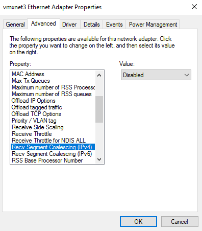
To access the adapter’s advanced properties using Windows 2016 (other versions may be slightly different) go to: Start > Settings > Network and Internet > Change adapter options, right click the adapter, select Properties, click Configure and then select the Advanced tab.
Using PowerShell
To disable RSC:
Disable-NetAdapterRsc -Name "net" -IPv4

or for IPv6

Disable-NetAdapterRsc -Name "net" -IPv6
To enable RSC:
Enable-NetAdapterRsc -Name "net" -IPv4

or for IPv6

Enable-NetAdapterRsc -Name "net" -IPv6
-
If your network adapter is not named "net" modify the command accordingly
Configuring Your Application to Respond to Both the RIP and VIP
For DR & TUN modes, it’s important to make sure that your application (IIS in this example) responds to both the VIP and RIP.
By default, IIS listens on all configured IP addresses as shown in the example below. As can be seen, the IP address field is set to "All Unassigned".
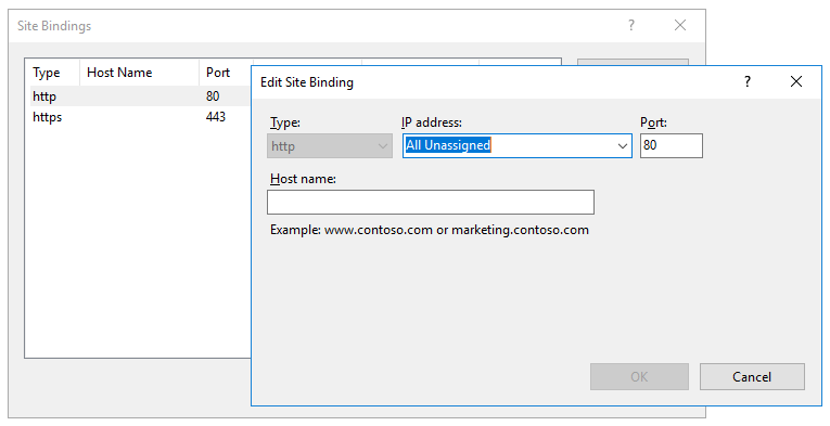
If the default setting is not changed, no further IIS configuration is required. If you do change the IP address in the bindings from "All Unassigned" to a specific IP address, then you need to make sure that you also add a binding for the Virtual Service IP address (VIP) as shown in the example below:
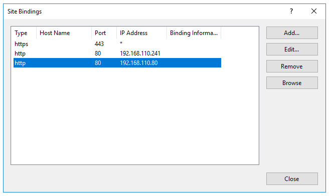
| This example illustrates how IIS must be configured to ensure that it’s listening on both the RIP and VIP address. Remember that this applies to ALL applications when using DR mode. |
Windows Firewall Settings
When IIS is installed, default rules are created that allow inbound traffic on port 80 and 443. By default, these rules apply to the Domain, Public and Private profiles and all interface types. If the rules are changed, make sure that inbound traffic can still reach both the LAN interface and the loopback adapter.
NAT Mode Considerations
Layer 4 NAT mode requires Real Server return traffic to pass back via the load balancer. This is achieved by setting each Real Server’s default gateway to be the load balancer. For an HA Pair, a floating IP address should be used to allow the gateway to "float" (move) between appliances should a failover occur.
Whilst NAT mode is fairly straight forward, certain points need to be considered.
NAT Mode Potential Issues
-
By default the Real Servers won’t be able to access the Internet through the new default gateway (except when replying to requests made through the external VIP).
-
Non-load balanced services on the Real Servers (e.g. RDP for management access to Windows servers) will not be accessible since these have not been exposed via the load balancer.
Enabling Access to non Load Balanced Services
If you want non load balanced services on your Real Servers to be accessible from the external subnet, options include:
-
Configure a SNAT mode Virtual Service listening on the relevant service port(s) and add the required Real Server leaving the Real Server Port field blank.
-
Configure a DNAT mode Virtual Service listening on the relevant service port(s) and add the required Real Server leaving the Real Server Port field blank. The Real Server’s default gateway must be the load balancer.
One-Arm (Single Subnet) NAT Mode
Normally the VIP is located on a different subnet to the Real Servers. However, it is possible to perform NAT mode load balancing on a single subnet where the VIP is brought up in the same subnet as the Real Servers. For clients located on this subnet, return traffic would normally be sent directly to the client bypassing the load balancer which would break NAT mode. To address this, the routing table on the Real Servers must be modified to force return traffic to pass via the load balancer. The sections below explain how routing must be modified for Windows hosts and Linux hosts.
Route Configuration for Windows Servers
To rectify this issue for Windows servers, a route must be added to each Real Server that takes priority over the default Windows routing rules. This is a simple case of deleting the default On-link route and adding a permanent route via the load balancer using the following commands on each real server:
netsh interface ipv4 delete route 192.168.2.0/24 "LAN"
netsh interface ipv4 add route 192.168.2.0/24 "LAN" 192.168.2.21
| Replace "192.168.2.0/24" with your subnet address, "192.168.2.21" with your load balancer’s IP address and "LAN" with the name of the interface on your server. |
| After running the above commands, reboot the server and check if the updated routing rules have remained. Depending on the specific version of Windows, it may be necessary to add the commands to a startup script. This is because under certain circumstances routing rules for on-link, directly accessible addresses can get reset to defaults after a reboot. |
Verify routing rules using the following command:
netsh interface ipv4 show route
Route Configuration for Linux Servers
To rectify this issue for Linux servers, the local network route must be changed to a higher metric:
route del -net 192.168.2.0 netmask 255.255.255.0 dev eth0
route add -net 192.168.2.0 netmask 255.255.255.0 metric 2000 dev eth0
| Ensure you specify your local subnet address. |
Then we must ensure that local network access uses the load balancer as its default route:
route add -net 192.168.2.0 netmask 255.255.255.0 gateway 192.168.2.21 metric 0 dev eth0
| Replace 192.168.2.0 & 255.255.255.0 with your local subnet address and replace 192.168.2.21 with the IP address of your load balancer. |
Any local traffic (same subnet) is then handled by the manual route and any external traffic is handled by the default route (which also points at the load balancer).
Layer 7 Services
Introduction
Layer 7 services are based on HAProxy which is a fast and reliable proxying and load balancing solution for TCP, HTTP/1.1 and HTTP/2 applications.
Since HAProxy is a full proxy, Layer 7 services are not transparent by default, i.e. the client source IP address is lost as requests pass through the load balancer and instead are replaced by an IP address owned by the load balancer. This is the interface IP by default, but can also be set to any other IP address that the load balancer owns, for example the VIP address.
Multiple persistence methods (aka affinity/stickiness) are supported and can be enabled when needed.
Multiple ports can be specified, for example 80 & 443. In this case persistence is useful to ensure that clients hit the same backend server for both HTTP & HTTPS traffic and also prevent the client having to renegotiate the SSL connection.
| It’s not possible to configure a VIP on the same IP address as any of the network interfaces. This ensures services can "float" (move) between nodes when using an HA cluster. |
Adding Layer 7 Virtual Services
Layer 7 Services are configured using a template based wizard. The wizard is split into 2 stages: Frontend Configuration (the Virtual Service that clients connect to) and Backend Configuration (the pool of Real Servers that requests are distributed to).
The wizard can be run in 2 modes, selected using the drop-down at the top of the left-hand menu:
| Mode | Description |
|---|---|
Default Mode |
Displays only the most commonly used settings. Recommended for a quick, standard deployment. |
Advanced Mode |
Displays all available settings, including the additional HTTP connection frontend step and the full set of backend options. |
| The steps below use Advanced Mode so that all available settings are described. When using Default Mode, the advanced settings are hidden and sensible defaults are applied automatically. |
To add a new Layer 7 Service:
-
Using the WebUI, navigate to Cluster Configuration > Manage Services and click Add service.
-
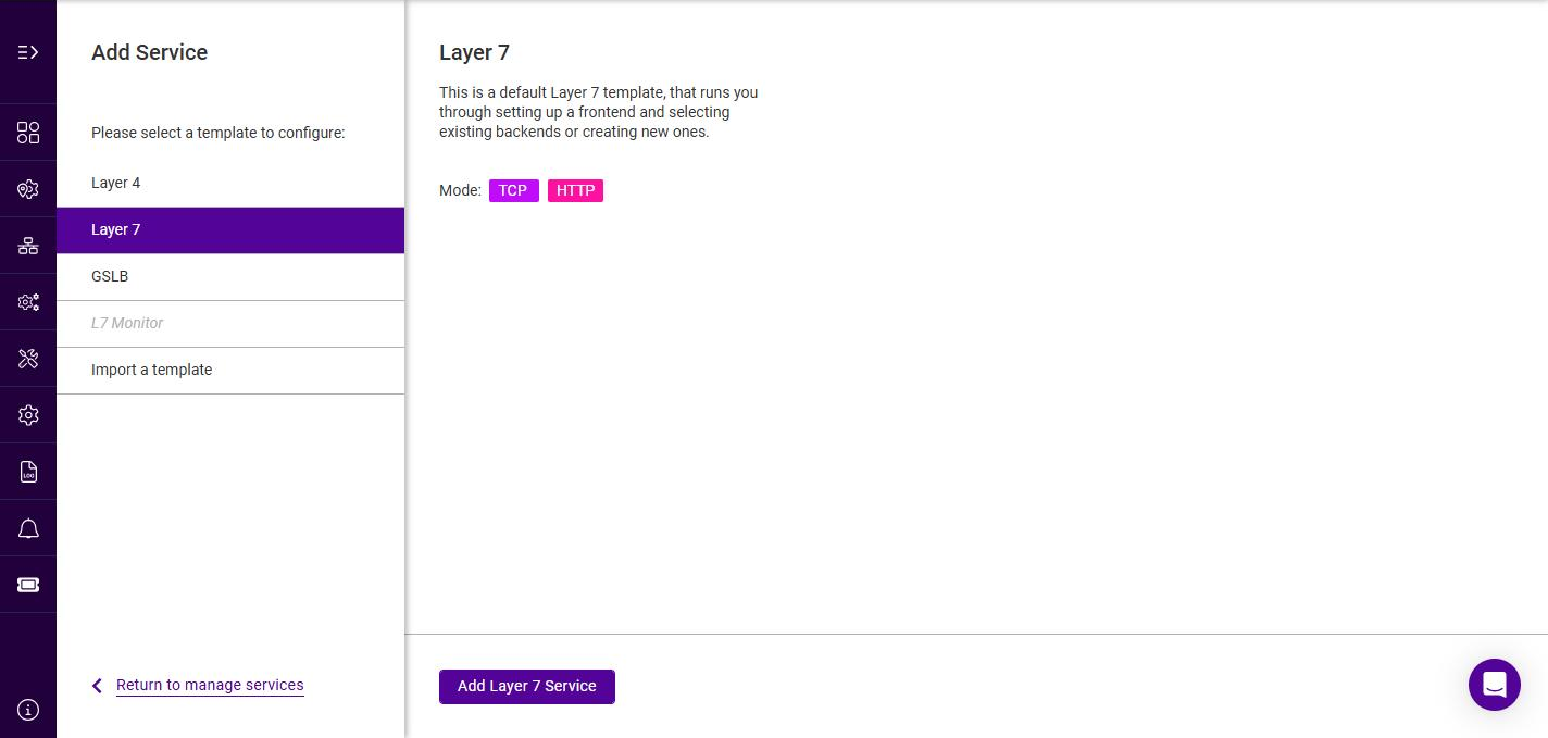
Select the Layer 7 template, then click Add Layer 7 Service.
-
To display all settings, change the mode drop-down from Default Mode to Advanced Mode.
Frontend Configuration - General
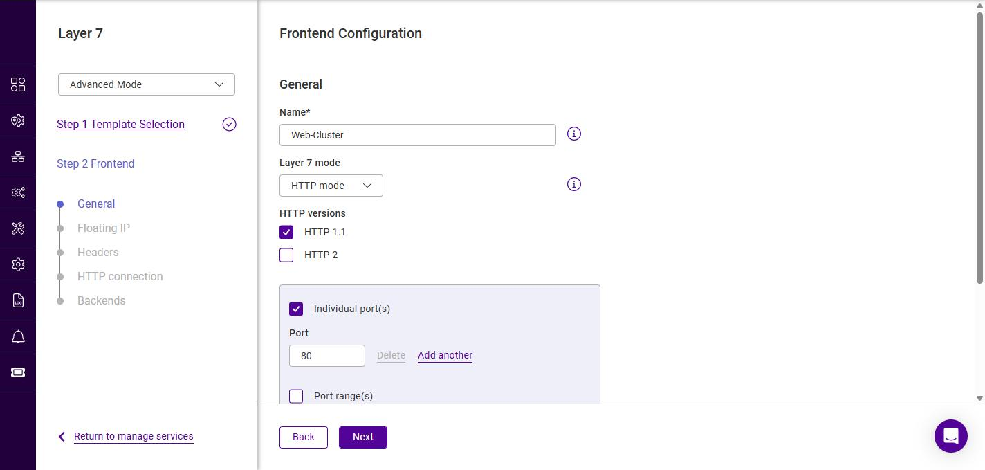
-
Specify a suitable Name for the service, e.g. Web-Cluster.
-
Select the required Layer 7 mode, the options are:
Layer 7 mode Description HTTP mode
Use this mode if the Virtual Service will handle only HTTP traffic. This allows more flexibility in the processing of connections. When using persistence types such as HTTP Cookie, HTTP mode must be selected. In addition, the HAProxy log will show more information on the client requests and Real Server responses.
TCP mode
Use this mode to support all non-HTTP traffic such as HTTPS, RPC, RDP, FTP, SIP etc.
-
For HTTP mode Services, select the required HTTP versions (HTTP 1.1 and/or HTTP 2).
-
Specify the port(s) that the service should listen on:
-
Use Individual port(s) to specify one or more discrete ports. Click Add another to add additional ports.
-
Use Port range(s) to specify a contiguous range of ports.
-
-
Under SSL ports, the following additional options are available:
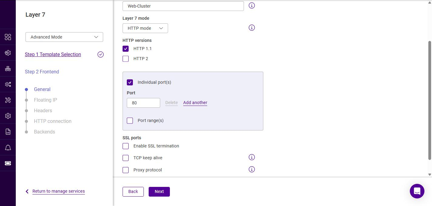
Setting Description Enable SSL termination
When enabled, the load balancer terminates the SSL/TLS connection. A separate set of HTTPS port(s) is exposed, and 2 additional wizard steps (SSL and Certificates) are added to the Frontend Configuration. For more information, see SSL/TLS Termination - Concepts.
TCP keep alive
Enables the transmission of TCP keep-alive packets on both the client and the server sides of the connection.
Proxy protocol
Configures the Layer 7 VIP to expect Proxy Protocol headers for all incoming connections.
Enabling SSL termination reveals an Individual port(s) / Port range(s) field for the HTTPS port(s). This must not clash with the plain-text port specified above, e.g. set the SSL port to 443. 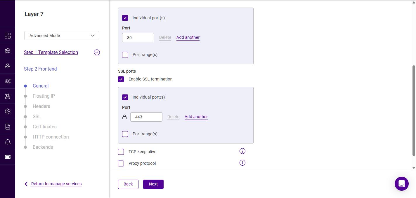
-
Click Next.
Frontend Configuration - Floating IP
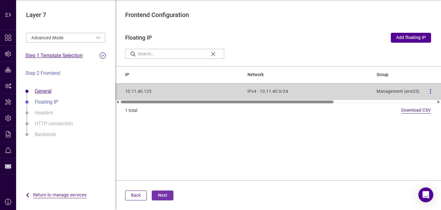
The Floating IP (FIP) is the address that clients connect to. The list shows all configured Floating IPs.
-
If the required Floating IP already exists, click its row to select it (the row is highlighted when selected).
-
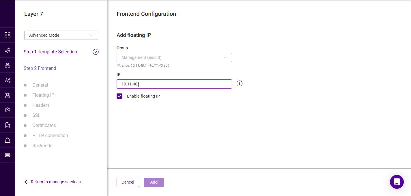
If the required Floating IP does not exist, click Add floating IP.
-
Select the Group (IP group / subnet) in which the Floating IP should be brought up. The valid IP range for the selected group is displayed below the field.
-
Specify a suitable IP address for the service, e.g. 10.11.40.125.
-
Leave Enable floating IP checked to bring the address up on the interface immediately.
-
Click Add.
Floating IPs can also be managed independently under Network > Floating IPs.
-
-
Ensure the required Floating IP is selected, then click Next.
Frontend Configuration - Headers
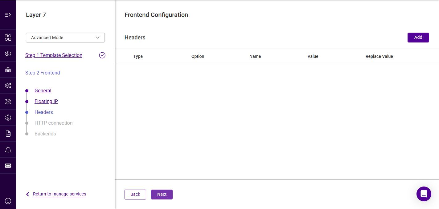
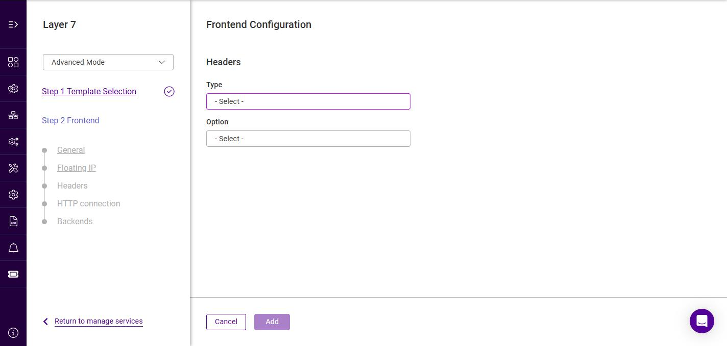
For HTTP mode Services, HTTP header rules can be added, set, deleted, and replaced. The Headers step is optional - to skip it, simply click Next.
-
To add a header rule, click Add.
-
Select the header Type, the options are:
Type Description Request
Affect specified HTTP header fields in HTTP request messages.
Response
Affect specified HTTP header fields in HTTP response messages.
-
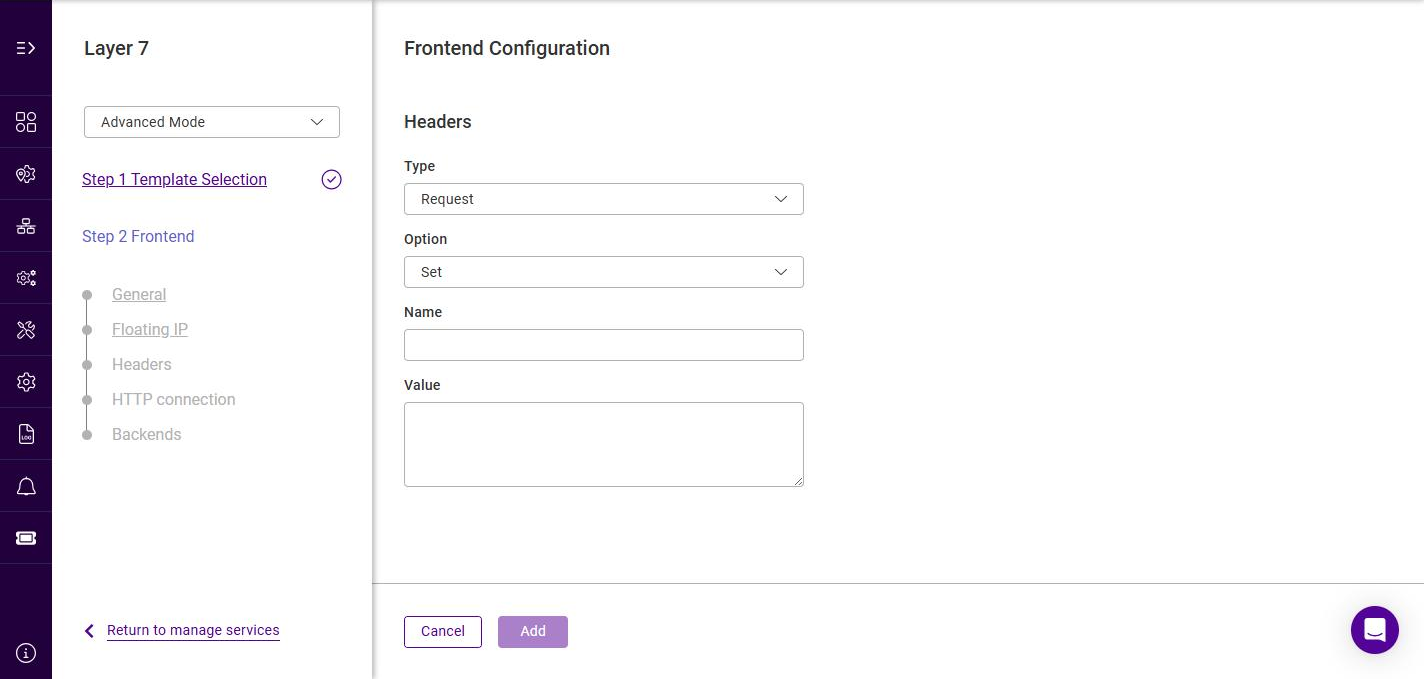
Select the required Option, the options are:
Option Description Add
Append an HTTP header field. If a header field of the same name already exists then an additional header field will still be appended.
Set
Append an HTTP header field. If a header field of the same name already exists then it is first removed before a new one is appended. This is useful for handling security information which external users must not be able to set themselves.
Delete
Remove all HTTP header fields of a specified name.
Replace
Perform a regular expression powered "find and replace" operation on all HTTP header field values of a specified name.
-
Specify the required Name and Value (and Replace Value for the Replace option).
-
Click Add, and repeat to add additional header rules.
For examples of using headers, see HTTP Headers - Configuration Examples. -
Click Next.
|
The SSL and Certificates steps described below are only displayed when Enable SSL termination was selected on the General step. If SSL termination was not enabled, the wizard proceeds directly to the HTTP connection step. |
Frontend Configuration - SSL
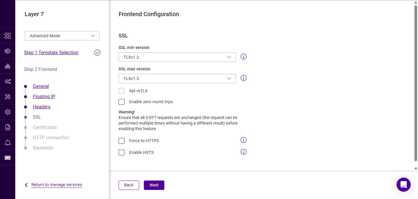
This step controls how the load balancer terminates the SSL/TLS connection presented to clients.
-
Configure the SSL settings as required:
Setting Description SSL min version
The minimum TLS protocol version the load balancer will negotiate with clients. The options are TLSv1.0, TLSv1.1, TLSv1.2 (default) and TLSv1.3.
SSL max version
The maximum TLS protocol version the load balancer will negotiate with clients. The options are TLSv1.0, TLSv1.1, TLSv1.2 and TLSv1.3 (default).
Set mTLS
Enables mutual TLS (mTLS), requiring clients to present a valid client certificate. The CA certificate(s) used to validate client certificates must be available on the appliance - see CA Certificates.
Enable zero round trips
Enables TLS 1.3 0-RTT (zero round trip time) early data, reducing latency for resumed sessions.
Warning: ensure that all 0-RTT requests are idempotent (the request can be performed multiple times without producing a different result) before enabling this feature.Force to HTTPS
Automatically redirects plain-text HTTP requests received on the service to HTTPS. See also [HTTP to HTTPS Redirection].
Enable HSTS
Adds an HTTP Strict Transport Security (HSTS) response header, instructing browsers to only connect to the service over HTTPS.
For background on the SSL termination modes (SSL offloading, SSL bridging, SSL passthrough), see SSL/TLS Termination - Concepts. -
Click Next.
Frontend Configuration - Certificates
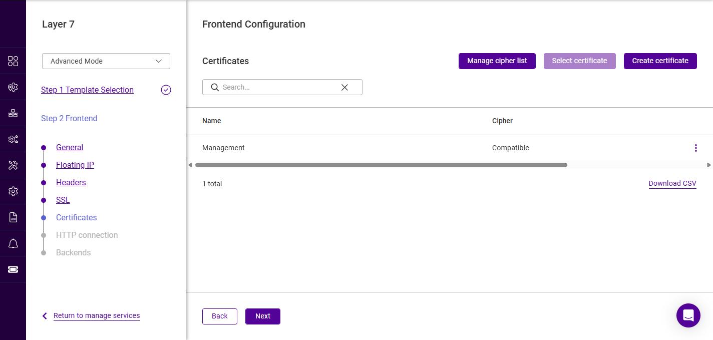
This step selects the SSL certificate(s) that the service presents to clients, together with the cipher list to use. At least one certificate must be added before the wizard can continue.
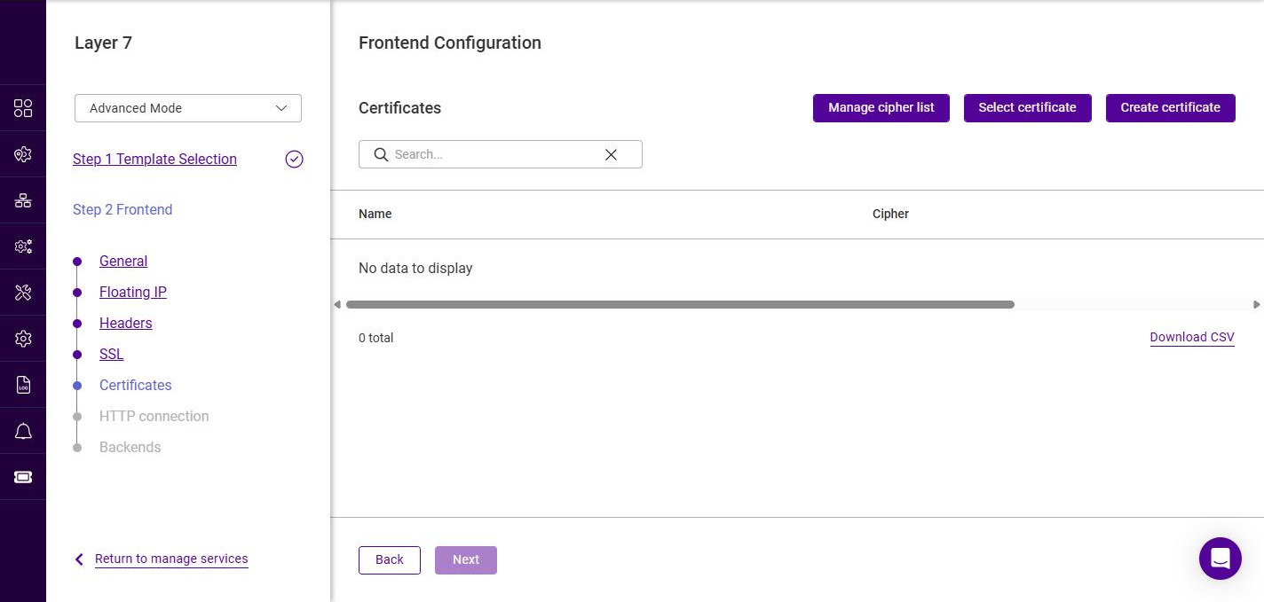
The following actions are available:
| Action | Description |
|---|---|
Manage cipher list |
Opens the cipher list manager, where the predefined cipher lists can be viewed and custom lists created. See SSL cipher lists. |
Select certificate |
Associates an existing certificate (and a cipher list) with this service - see below. |
Create certificate |
Opens the SSL certificate manager so that a new certificate can be uploaded or generated - see below. |
Selecting an existing certificate
-
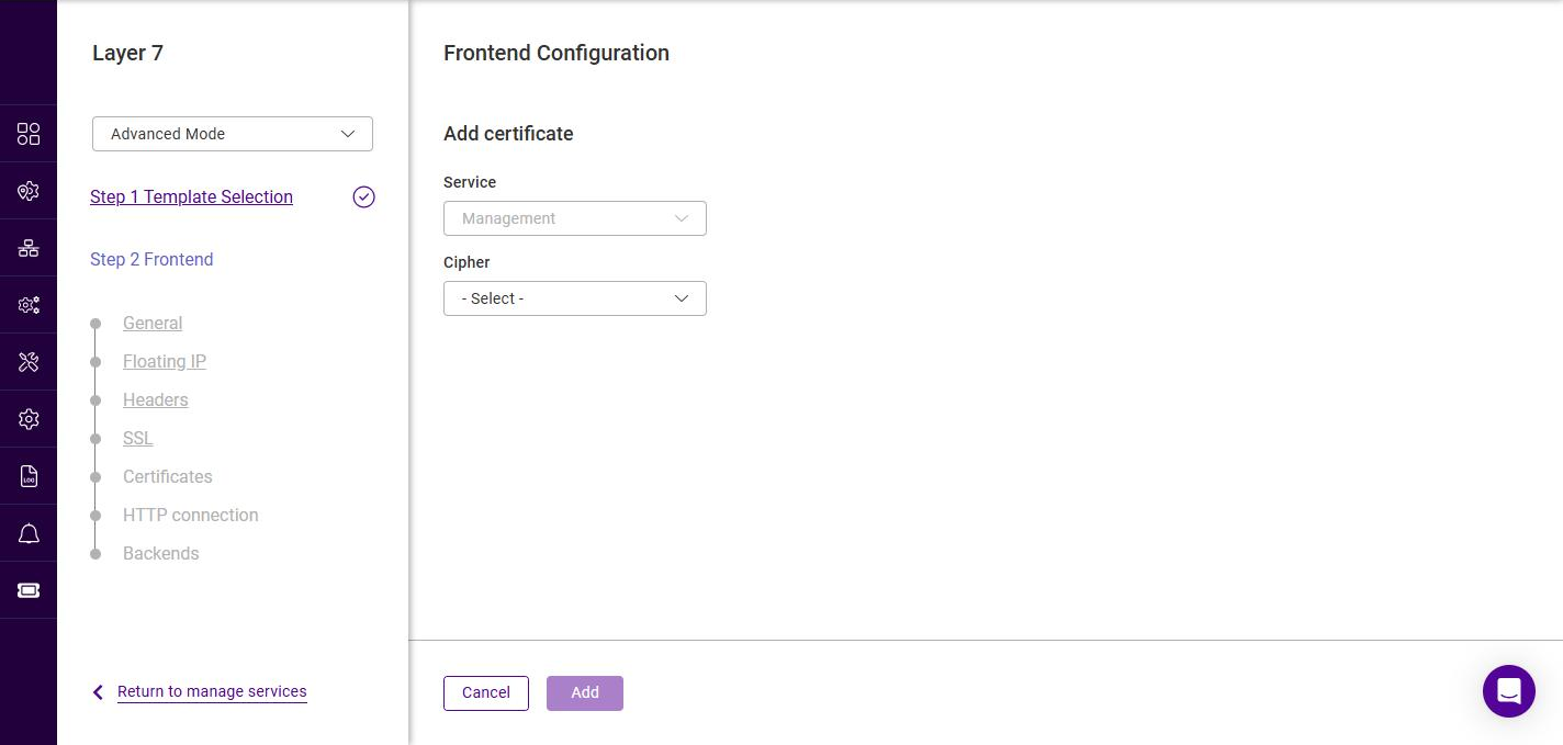
Click Select certificate.
-
Select the certificate to present in the Service field.
-
Select the required Cipher list. The predefined lists are:
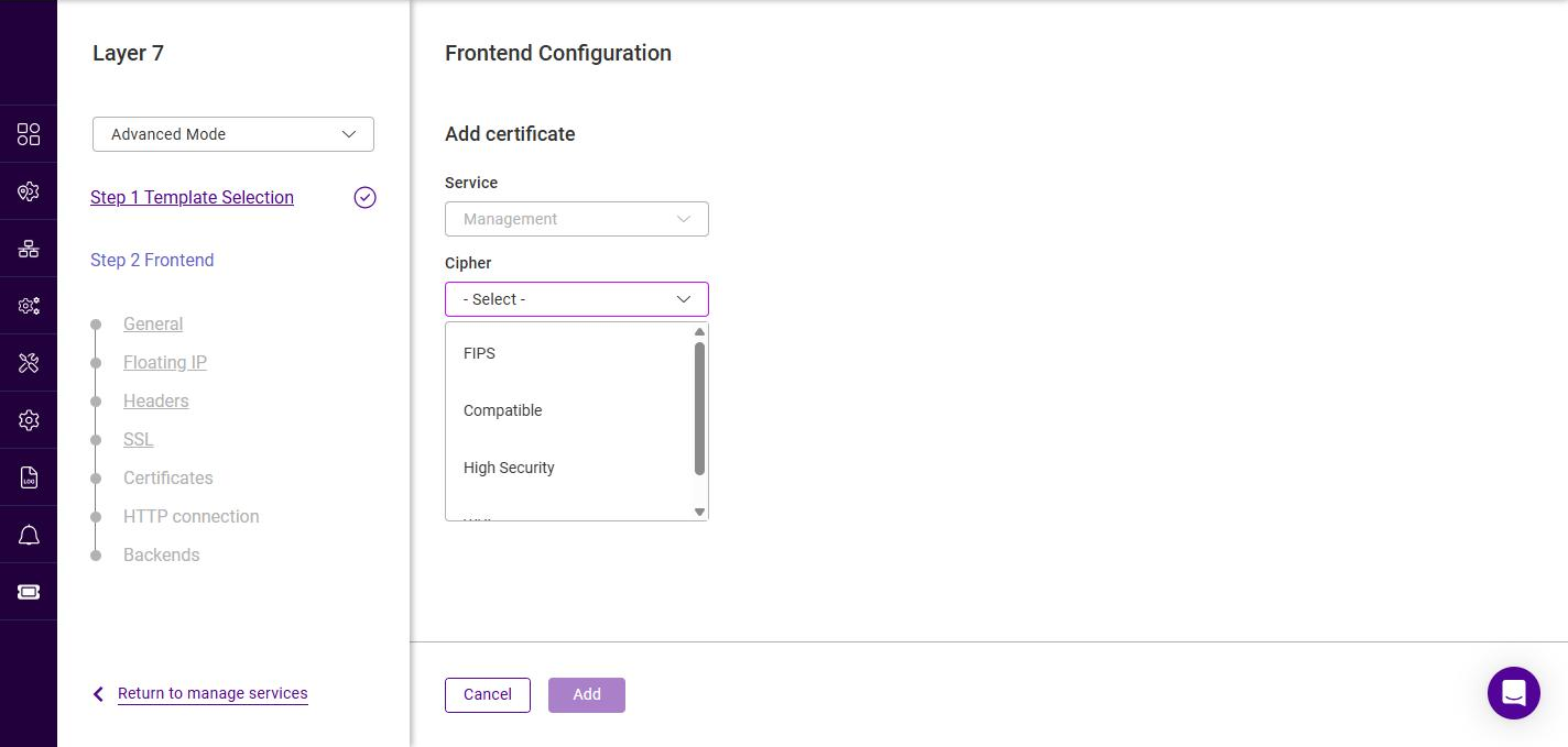
Cipher list Description FIPS
A FIPS 140-2 compliant cipher list.
Compatible
A broad cipher list that maximizes compatibility with older clients.
High Security
A restricted cipher list offering the strongest security, at the expense of compatibility with older clients.
WUI
The cipher list used by the appliance WebUI.
For details on creating and modifying custom cipher lists, see SSL cipher lists. -
Click Add. The certificate is added to the list for this service.
Creating a new certificate
If the required certificate does not yet exist, click Create certificate. This opens the SSL certificate manager (with Certs, CSR, CA and CRL tabs) where certificates can be uploaded or generated.
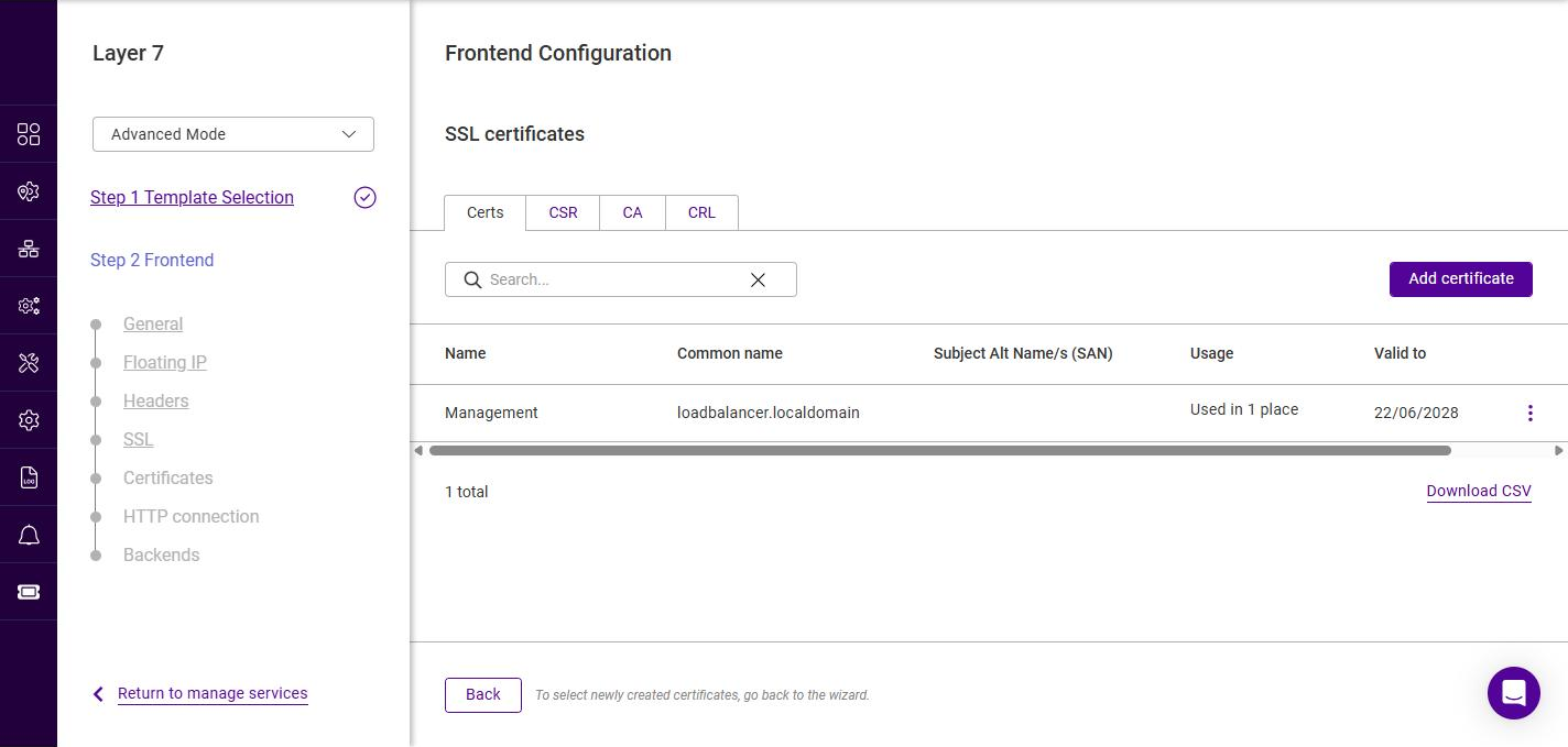
Once the certificate has been created, click Back to return to the wizard, then use Select certificate to associate it with the service. For full details on generating a CSR, uploading certificates and creating PEM files, see SSL Certificates.
-
Once at least one certificate has been added, click Next.
Frontend Configuration - HTTP connection
This step is only shown in Advanced Mode for HTTP mode Services.
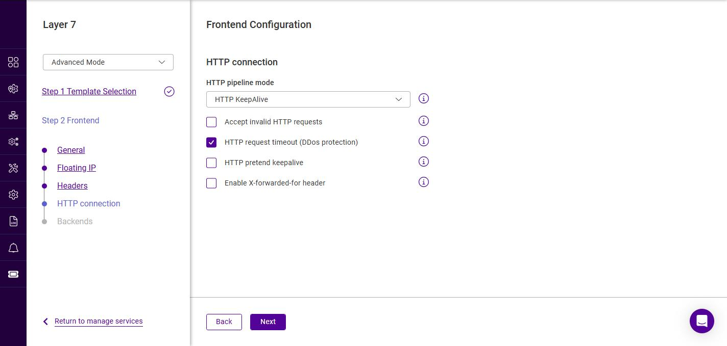
-
Configure the connection handling options as required:
Setting Description HTTP pipeline mode
Controls how connections are kept open. The options are HTTP KeepAlive (default), Http Close and HTTP Server Close.
Accept invalid HTTP requests
Allows non-standard requests that would otherwise be rejected.
HTTP request timeout (DDoS protection)
Enables a timeout on the receipt of the full HTTP request, providing protection against slow-request (DDoS) attacks. Enabled by default.
HTTP pretend keepalive
The load balancer presents a keep-alive connection to the client while using a close connection to the Real Server.
Enable X-forwarded-for header
Adds an X-Forwarded-For header containing the client source IP address to requests sent to the Real Servers.
-
Click Next.
Frontend Configuration - Backends
The Backends step lists the backends (Real Server pools) associated with this frontend.
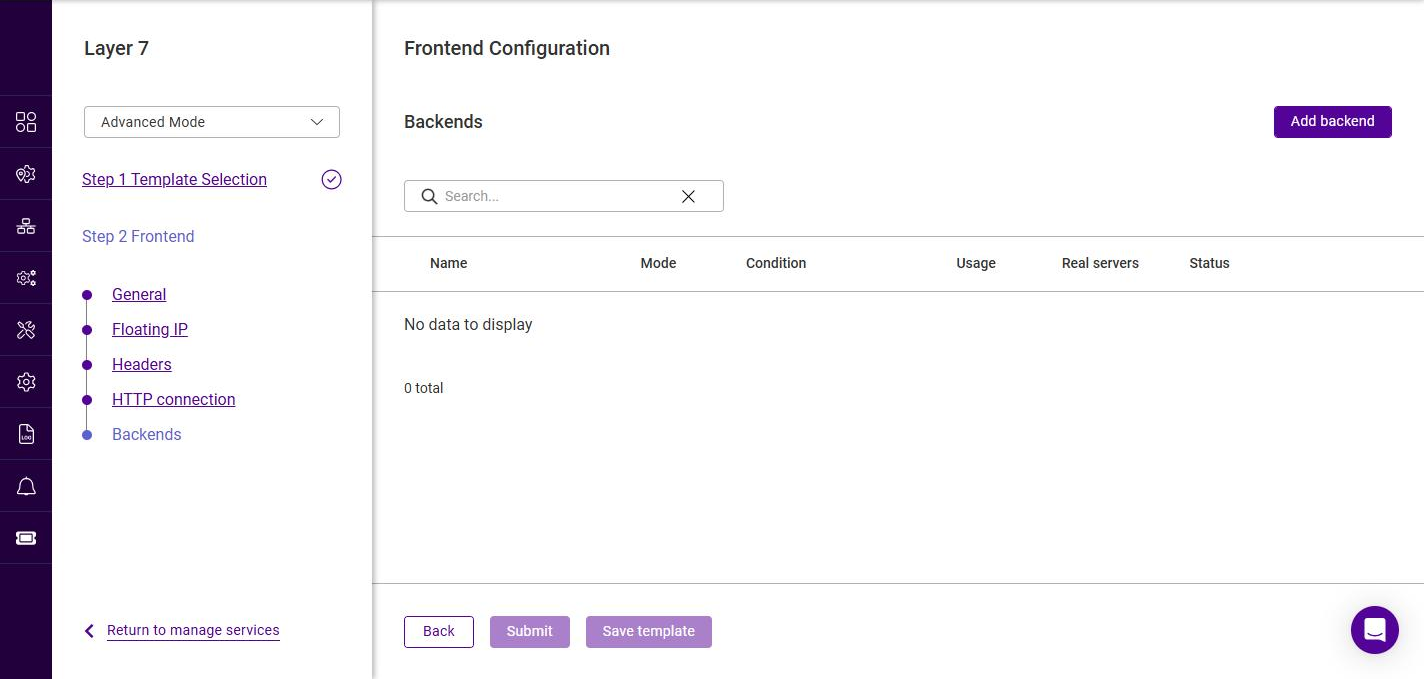
-
Click Add backend to define a new backend. This opens the Backend Configuration wizard described below.
Backend Configuration - General
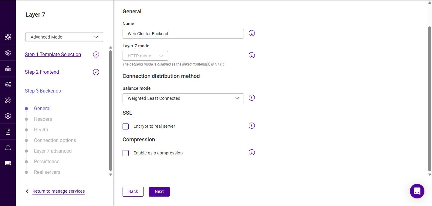
-
Specify a suitable Name for the backend, e.g. Web-Cluster-Backend.
-
The Layer 7 mode is locked to match the linked frontend(s) and cannot be changed here.
-
Select the required Balance mode (the connection distribution method), the options are:
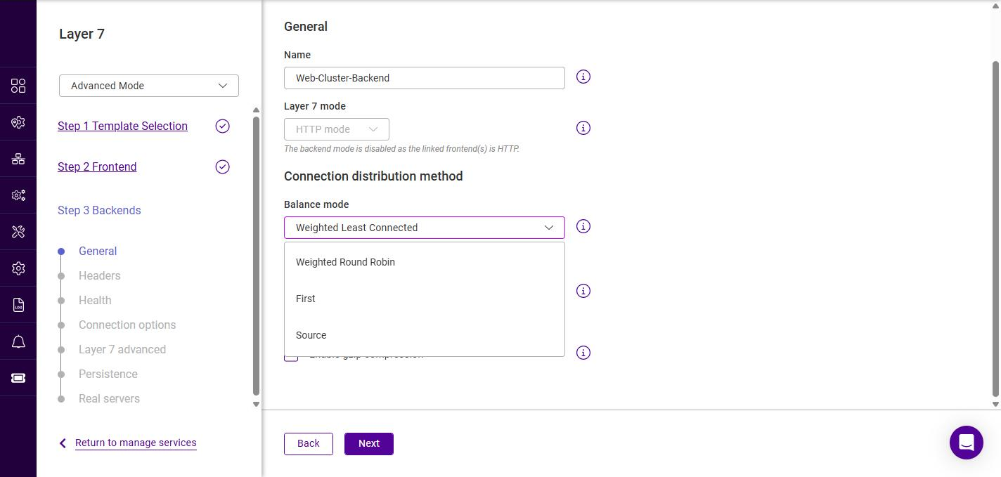
Balance mode Description Weighted Least Connected
New connections are sent to the Real Server with the fewest active connections, taking server weights into account. The default and recommended option.
Weighted Round Robin
Connections are distributed across the Real Servers in turn, taking server weights into account.
First
Connections are sent to the first available Real Server until it reaches its connection limit, then to the next, and so on.
Source
The Real Server is selected based on a hash of the client source IP address, providing a simple form of persistence.
-
If communication between the load balancer and the Real Servers must be encrypted, enable Encrypt to real server under SSL.
-
To compress responses, enable Enable gzip compression under Compression.
-
Click Next.
| The backend also has a Headers step, identical in operation to the frontend Headers step described above. Configure backend header rules if required, then click Next. |
Backend Configuration - Health
This step configures the health checks the load balancer uses to decide whether each Real Server is available. When a Real Server fails its health check it is marked down and traffic is redirected to the remaining servers; once it passes again it is automatically returned to service.
Layer 7 services are built on HAProxy. For low-level detail on the underlying health check directives (for example option httpchk, http-check expect, option mysql-check and the inter, rise and fall server keywords), refer to the HAProxy 2.4 configuration manual at docs.haproxy.org/2.4.
|
Default Mode and Advanced Mode
The fields shown on the Health step depend both on the selected Health check type and on whether the backend wizard is in Default Mode or Advanced Mode. The mode is set using the selector at the top-left of the wizard.
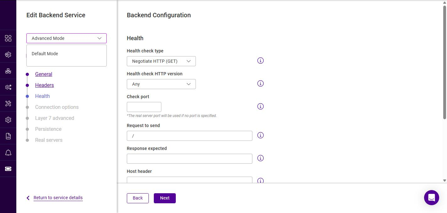
Default Mode shows only the essential fields for the selected check type. Advanced Mode additionally:
-
exposes the extra wizard steps Connection options and Layer 7 advanced (see the following sections), and
-
reveals the health check timing fields Interval, Rise and Fall for every check type, plus the Check port and Host header fields for the Negotiate checks.
Unless otherwise stated, the timing fields (Interval, Rise and Fall) described below are only available in Advanced Mode; in Default Mode the appliance defaults are used.
Selecting the health check type
-
Select the required Health check type:
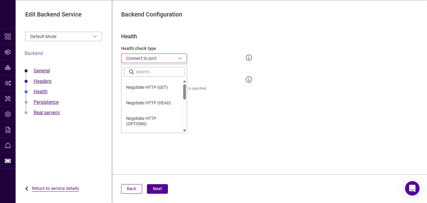
Health check type Description Connect to port
The default check. The load balancer opens a TCP connection to the check port; if the connection is accepted the Real Server is considered up. This is a fast, protocol-agnostic check suitable for any TCP-based service, but it only confirms that the port is open — not that the application behind it is healthy.
Negotiate HTTP (GET)
Sends an HTTP
GETrequest to the Real Server and marks it up only if the expected response is returned.GETretrieves the full page, allowing the returned content to be matched against the Response expected string. Use this when the health of the application — not just the port — must be verified.Negotiate HTTP (HEAD)
As Negotiate HTTP (GET), but sends a
HEADrequest.HEADreturns the same headers aGETwould return but without the response body, making it lighter weight while still confirming that the page is served.Negotiate HTTP (OPTIONS)
As Negotiate HTTP (GET), but sends an
OPTIONSrequest. The Real Server is marked up if the web server returns a validOPTIONSresponse. This is the lightest of the HTTP checks.Negotiate HTTPS (GET)
Identical to Negotiate HTTP (GET) but the request is sent over SSL/TLS. Use this when the Real Servers only accept encrypted connections.
Negotiate HTTPS (HEAD)
Identical to Negotiate HTTP (HEAD) but sent over SSL/TLS.
Negotiate HTTPS (OPTIONS)
Identical to Negotiate HTTP (OPTIONS) but sent over SSL/TLS.
External Script
Runs a custom script on the load balancer to determine Real Server health. Use this when none of the built-in checks can express the required test. The script must already exist on the appliance.
MySQL
Performs a MySQL-specific health check. The check completes a MySQL protocol handshake (and closes the session cleanly) without producing an error or aborted-connect entry on the database server. It requires a dedicated MySQL user — see the note below.
No checks, always on
Disables health checking entirely. All Real Servers are permanently considered up and traffic is sent to them regardless of their actual state. Use with caution.
Configuring the selected health check type
The fields that appear once a check type is selected are described below. Where the Default Mode and Advanced Mode views differ, both are shown.
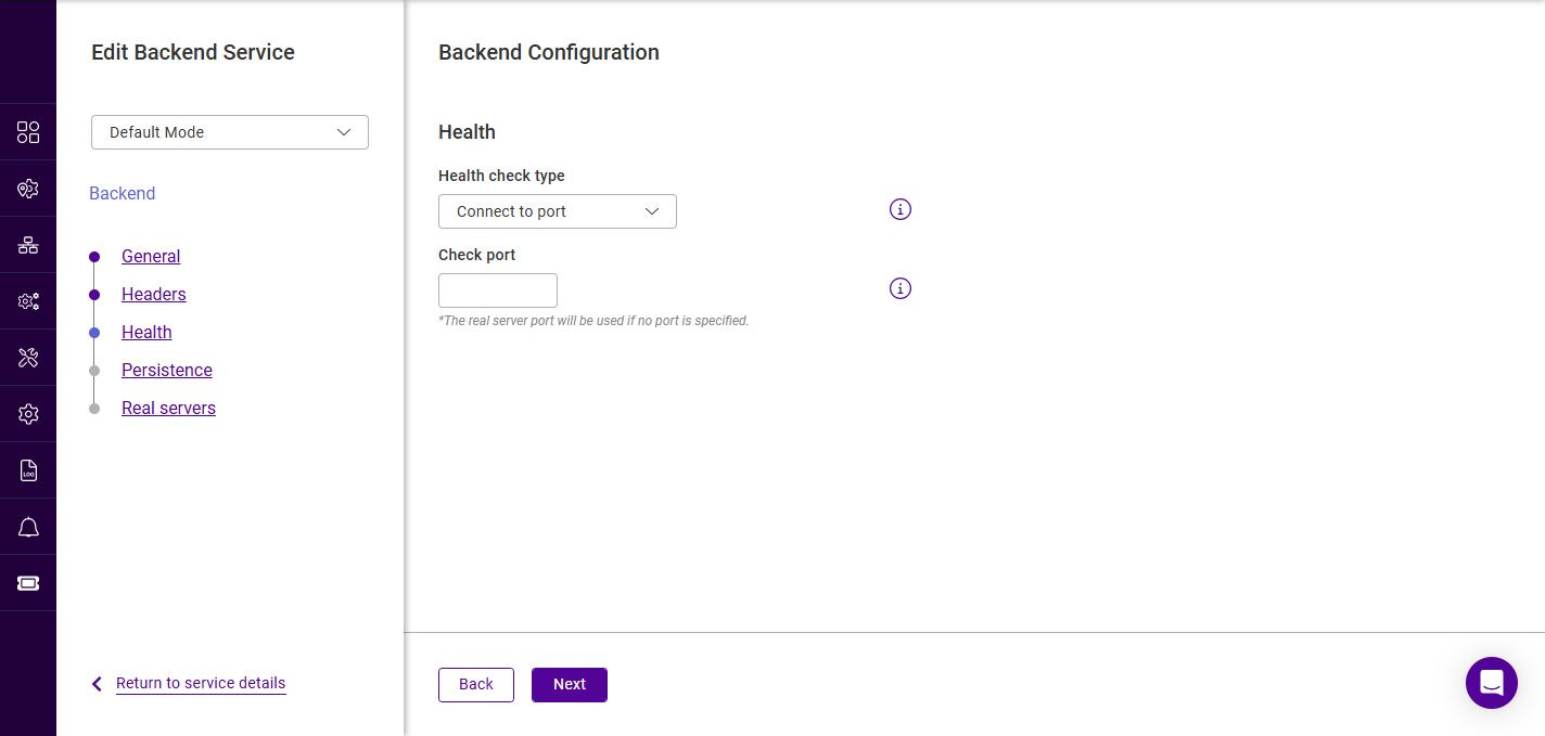
Connect to port
In Default Mode, only the Check port field is shown:
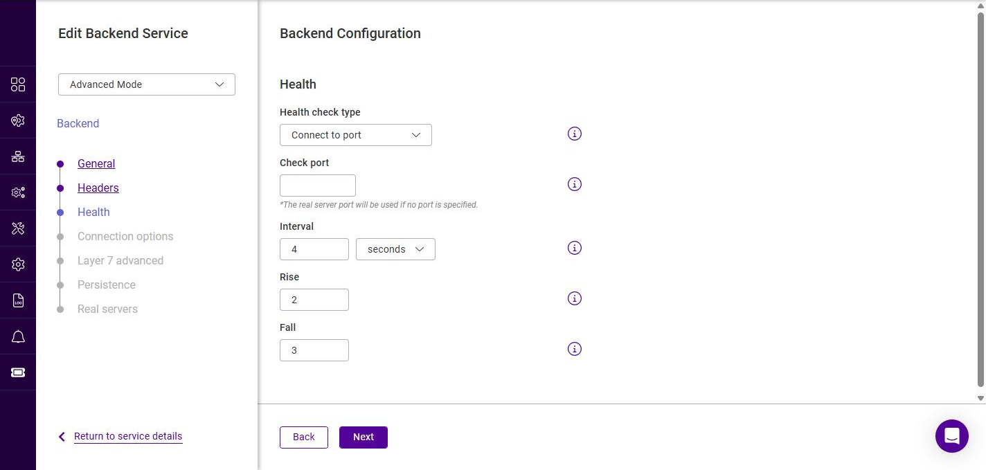
In Advanced Mode, the Interval, Rise and Fall timing fields are added:
| Setting | Description |
|---|---|
Check port |
The TCP port to connect to. If left blank, the Real Server port is used. |
Interval (Advanced) |
How often the health check is performed, specified as a value and unit (e.g. 4 seconds). |
Rise (Advanced) |
The number of consecutive successful checks required before a Real Server is marked up. |
Fall (Advanced) |
The number of consecutive failed checks required before a Real Server is marked down. |
Negotiate HTTP / HTTPS (GET / HEAD / OPTIONS)
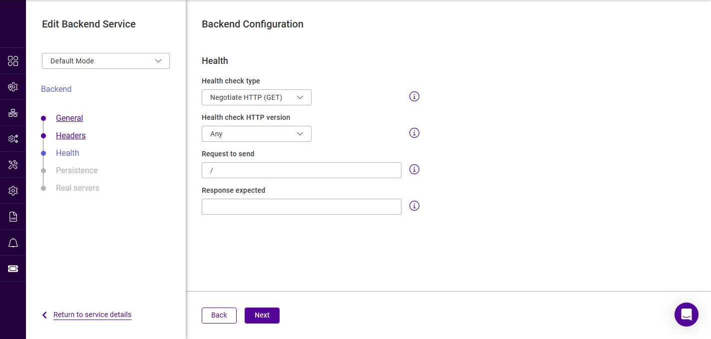
The six Negotiate check types share the same set of fields; only the protocol (HTTP or HTTPS) and request method (GET, HEAD or OPTIONS) differ. In Default Mode the following fields are shown:
In Advanced Mode the Check port, Host header, Interval, Rise and Fall fields are added:
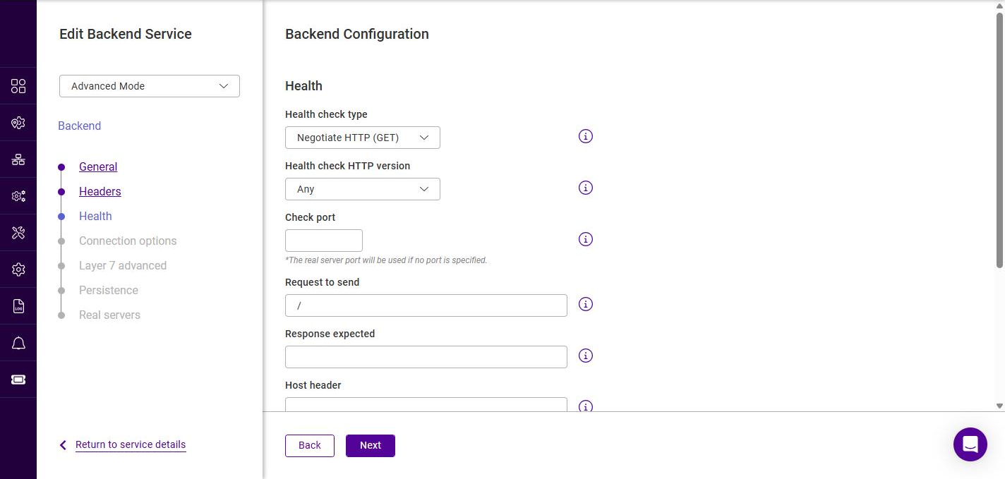
| Setting | Description |
|---|---|
Health check HTTP version |
The HTTP version used for the check request. The options are Any (default), HTTP/1.1 and HTTP/2. Select HTTP/1.1 or HTTP/2 if the Real Server requires a specific version. |
Request to send |
The URI requested by the check, e.g. |
Response expected |
An optional string that must be present in the response for the check to pass (for example an HTTP status code such as |
Check port (Advanced) |
The port to send the check request to. If left blank, the Real Server port is used. |
Host header (Advanced) |
The value of the |
Interval (Advanced) |
How often the health check is performed (value and unit). |
Rise (Advanced) |
The number of consecutive successful checks required before a Real Server is marked up. |
Fall (Advanced) |
The number of consecutive failed checks required before a Real Server is marked down. |
External Script
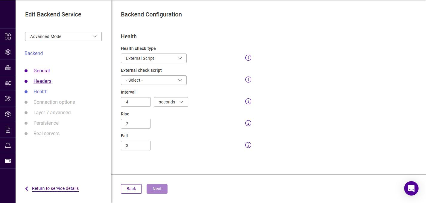
The External Script check runs a script stored on the appliance. In Advanced Mode the timing fields are also shown:
| Setting | Description |
|---|---|
External check script |
Selects the script used to determine Real Server health, from the scripts available on the appliance. The script’s exit status determines whether the server is considered up or down. |
Interval (Advanced) |
How often the script is run (value and unit). |
Rise (Advanced) |
The number of consecutive successful runs required before a Real Server is marked up. |
Fall (Advanced) |
The number of consecutive failed runs required before a Real Server is marked down. |
MySQL
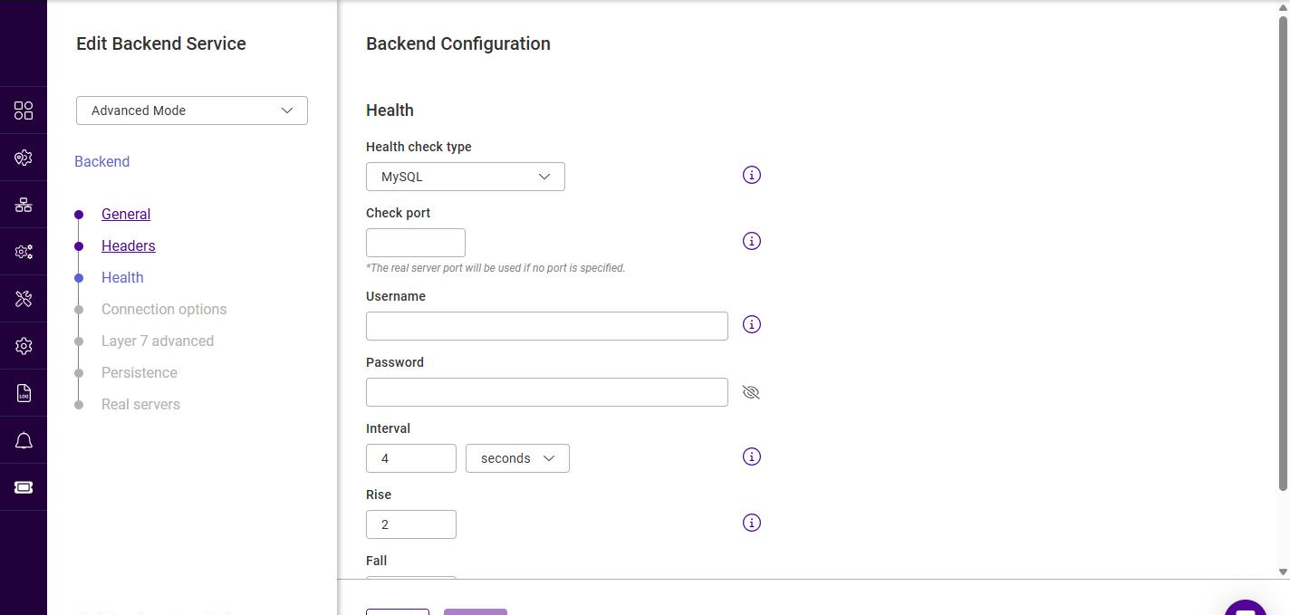
The MySQL check verifies that a MySQL database server is responding. In Advanced Mode the timing fields are also shown:
| Setting | Description |
|---|---|
Check port |
The port the MySQL server is listening on. If left blank, the Real Server port is used. |
Username |
The MySQL user the check authenticates as. |
Password |
The password for the MySQL user (leave blank if the user has no password). |
Interval (Advanced) |
How often the health check is performed (value and unit). |
Rise (Advanced) |
The number of consecutive successful checks required before a Real Server is marked up. |
Fall (Advanced) |
The number of consecutive failed checks required before a Real Server is marked down. |
| The MySQL check requires a user that is allowed to connect but needs no specific privileges. On the database server, such a user can be created with, for example: |
USE mysql;
INSERT INTO user (Host,User) values ('','');
FLUSH PRIVILEGES;
No checks, always on
This type has no additional fields. All Real Servers in the backend are permanently treated as up.
Once the health check has been configured, click Next.
Backend Configuration - Connection options
This step is only shown in Advanced Mode.
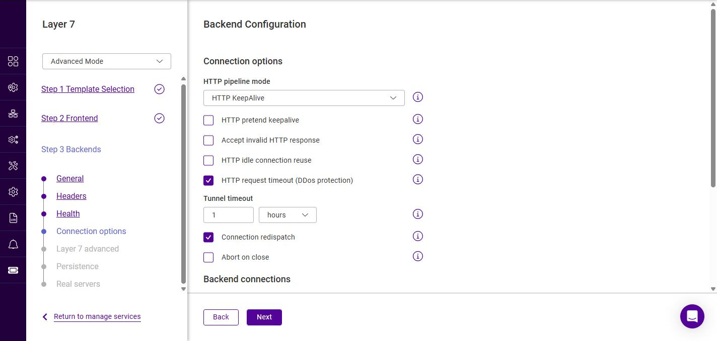
-
Configure the connection options as required:
Setting Description HTTP pipeline mode
Controls how backend connections are kept open (HTTP KeepAlive, Http Close, HTTP Server Close).
HTTP pretend keepalive
Presents a keep-alive connection to the client while using a close connection to the Real Server.
Accept invalid HTTP response
Allows non-standard responses from the Real Servers that would otherwise be rejected.
HTTP idle connection reuse
Allows idle backend connections to be reused for subsequent requests.
HTTP request timeout (DDoS protection)
Enables a timeout on the receipt of the full HTTP request. Enabled by default.
Tunnel timeout
The maximum inactivity time on a tunneled (e.g. WebSocket) connection (value and unit).
Connection redispatch
If a connection to a Real Server fails, the connection is redispatched to a different Real Server. Enabled by default.
Abort on close
Aborts the backend request if the client closes the connection before a response is received.
-
Under Backend connections, configure:
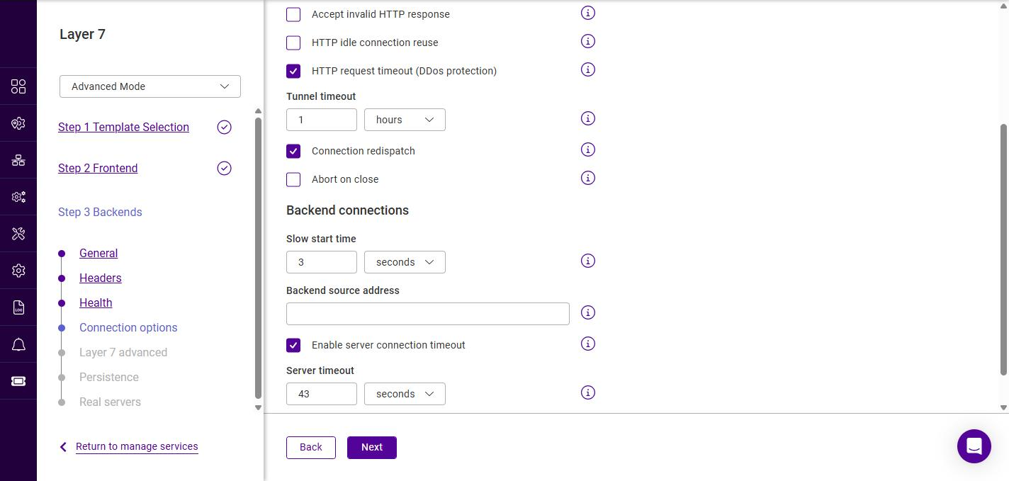
Setting Description Slow start time
The period over which a newly-online Real Server has its weight gradually ramped up to full (value and unit).
Backend source address
The source IP address used by the load balancer when connecting to the Real Servers. Leave blank to use the interface default.
Enable server connection timeout
Enables a timeout on the connection to the Real Servers.
Server timeout
The maximum inactivity time on the server side of the connection (value and unit).
-
Click Next.
Backend Configuration - Layer 7 advanced
This step is only shown in Advanced Mode and groups the feedback, fallback and proxy settings.
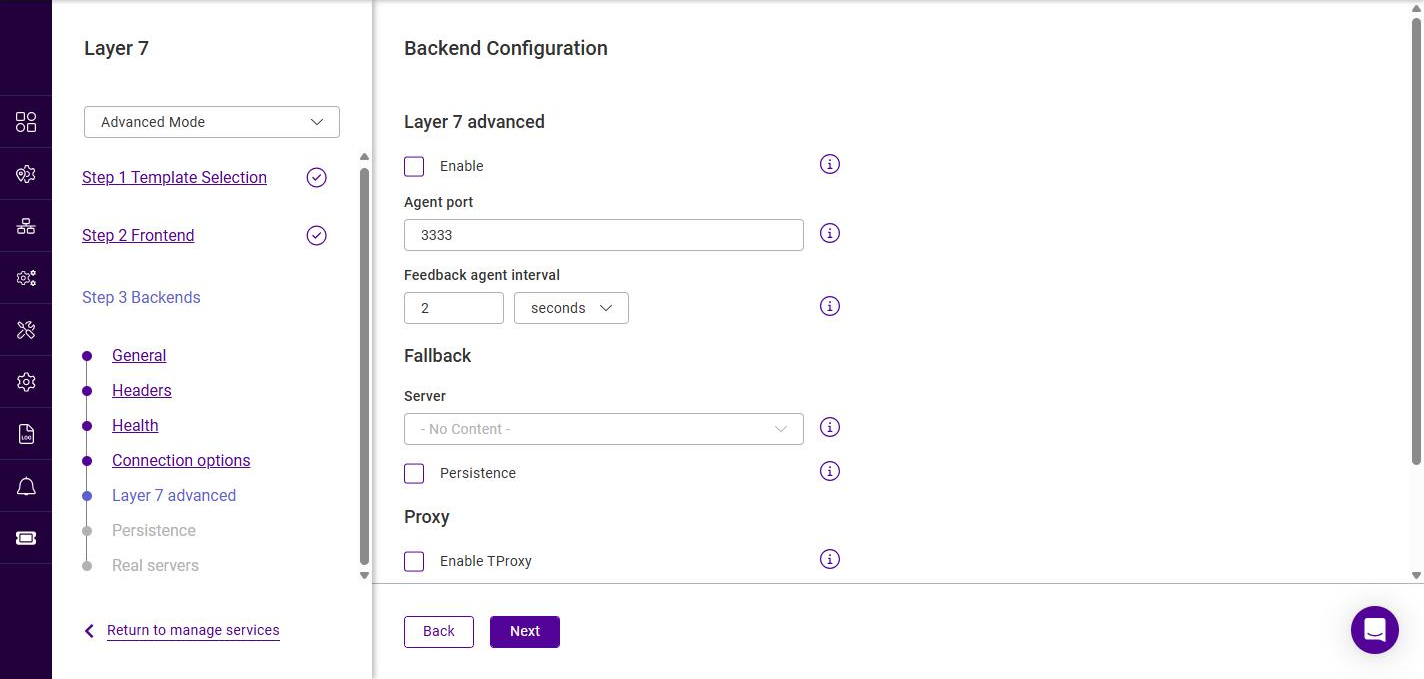
-
Configure the settings as required:
Section / Setting Description Layer 7 advanced - Enable
Enables the use of runtime data from the feedback agent installed on each Real Server to influence load balancing. For details on the feedback agent, see Server Feedback Agent.
Layer 7 advanced - Agent port
The port the feedback agent listens on. The default is 3333.
Layer 7 advanced - Feedback agent interval
How often the feedback agent is polled (value and unit).
Fallback - Server
The fallback (sorry) server presented to clients when all Real Servers in the backend are down.
Fallback - Persistence
Applies persistence to the fallback server.
Proxy - Enable TProxy
Enables transparent proxy so that the Real Servers see the original client source IP address. Requires the Real Servers to route return traffic via the load balancer.
Proxy - Send proxy protocol
Sends a Proxy Protocol header to the Real Servers. The options are Disabled (default), Send Proxy v1, Send Proxy v2, Send Proxy v2SSL and Send Proxy v2SSLCN.
-
Click Next.
Backend Configuration - Persistence
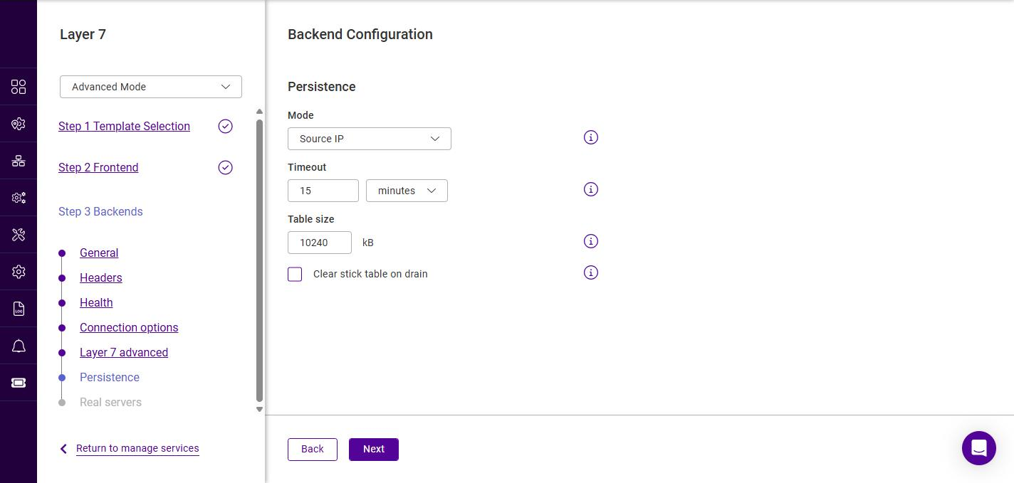
-
Select the persistence Mode:
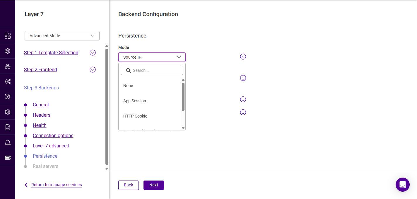
Mode Description None
No persistence; each request is load balanced independently.
App Session
Persistence based on an application session parameter.
Source IP
Clients are pinned to a Real Server based on their source IP address.
HTTP Cookie
Persistence is maintained using an HTTP cookie inserted by the load balancer.
HTTP Cookie and Source IP
Combines HTTP Cookie persistence with Source IP as a fallback.
X-Forwarded-For
Persistence based on the client address in the X-Forwarded-For header.
-
Configure the associated settings:
Setting Description Timeout
The persistence timeout. The timeout is reset on every new client connection (value and unit).
Table size
The size of the stick table used to record persistence entries.
Clear stick table on drain
Clears the persistence entries for a Real Server when it is drained.
-
Click Next.
Backend Configuration - Real servers
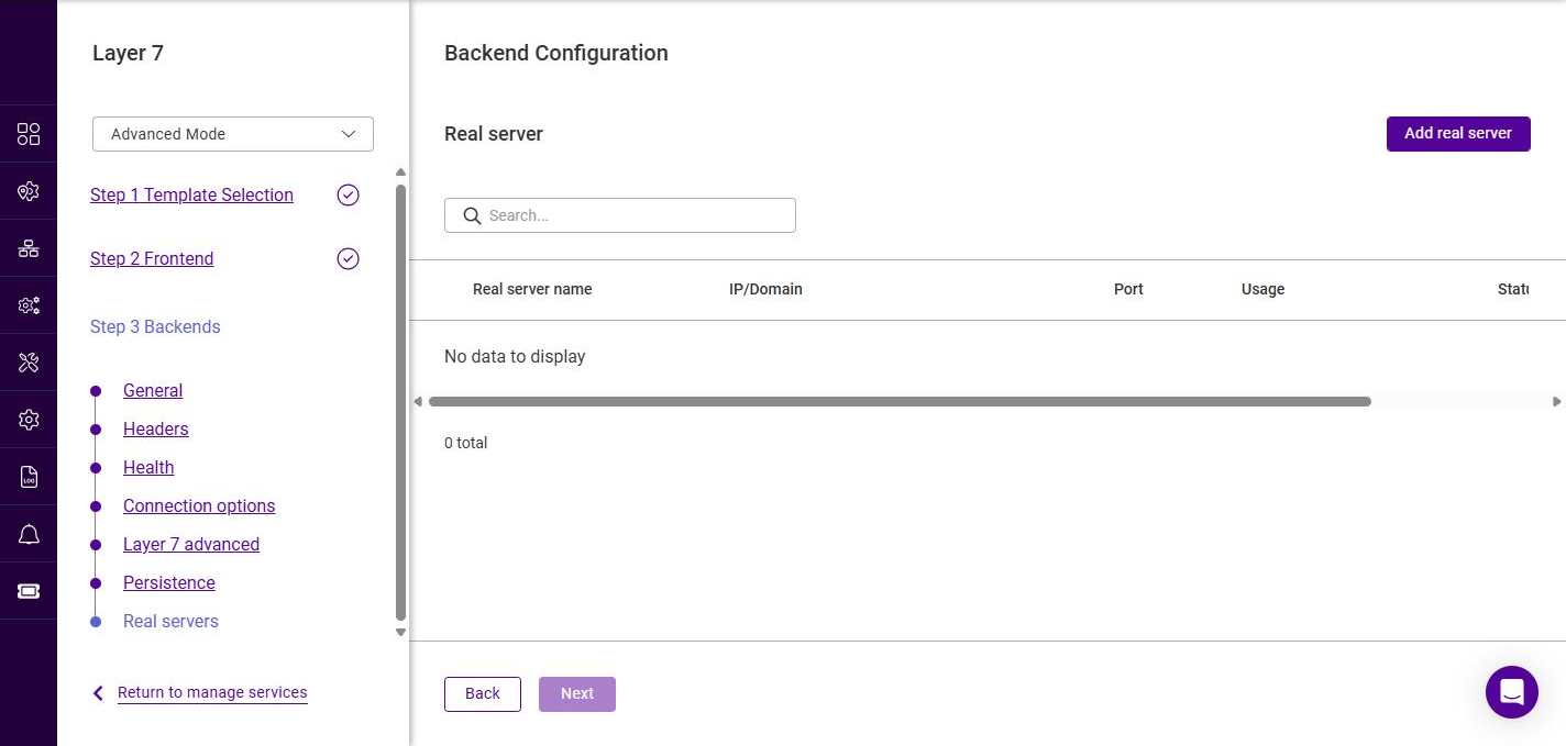
-
Click Add real server.
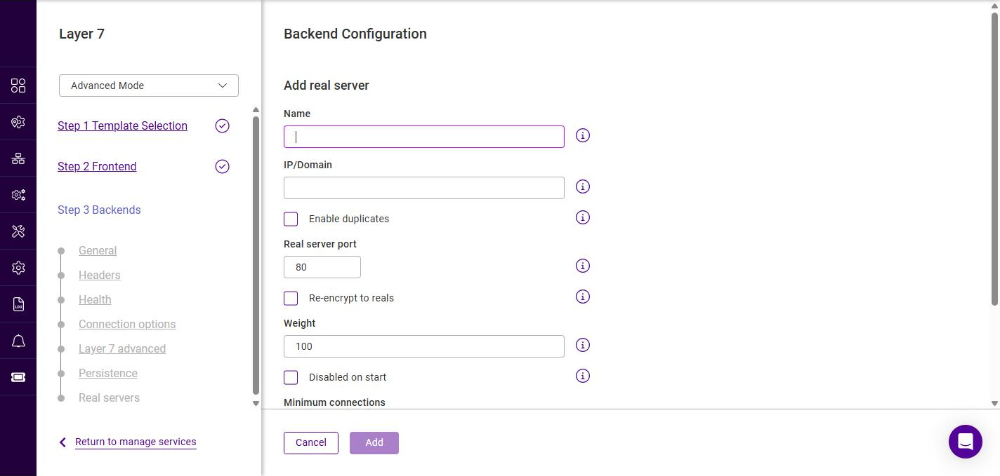
-
Configure the Real Server:
Setting Description Name
A suitable name for the Real Server, e.g. RS-01.
IP/Domain
The IP address or domain name of the Real Server, e.g. 10.11.40.10.
Enable duplicates
Allows the same IP/Domain to be added more than once (on different ports).
Real server port
The port the Real Server listens on. The default is 80.
Re-encrypt to reals
Re-encrypts traffic to this Real Server (used with SSL backends).
Weight
An integer specifying the capacity of the server relative to the others in the pool. Valid values are 0 to 65535, the default is 100. The higher the value, the more connections the server receives. A weight of 0 places the server in drain mode.
Disabled on start
Adds the Real Server in a disabled state.
Minimum connections
The lower connection threshold of the server. Valid values are 0 to 65535; 0 means not set.
Maximum connections
The upper connection threshold of the server. Valid values are 0 to 65535; 0 means not set.
-
Click Add, then repeat to add additional Real Servers, e.g. RS-02 / 10.11.40.20.
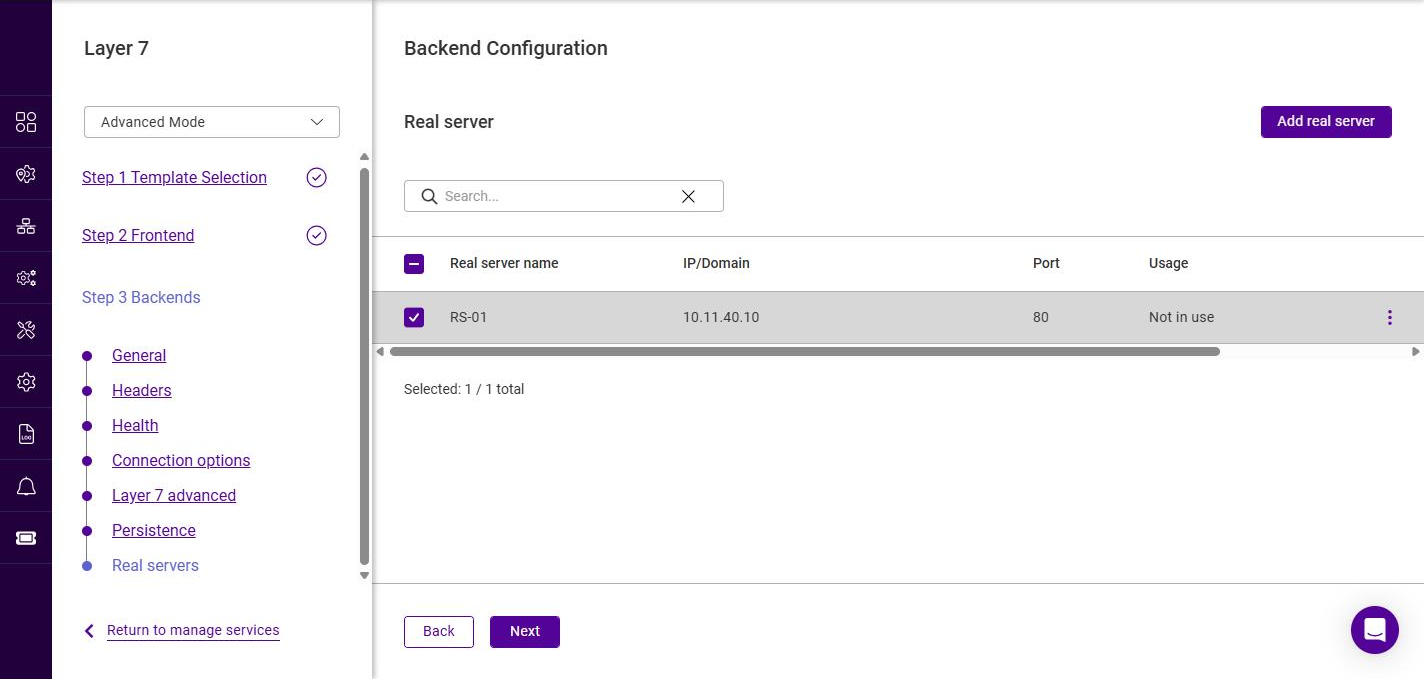
-
Ensure the required Real Servers are selected (checked), then click Next.
Submitting the Service
The newly defined backend is now shown in the frontend’s Backends list.
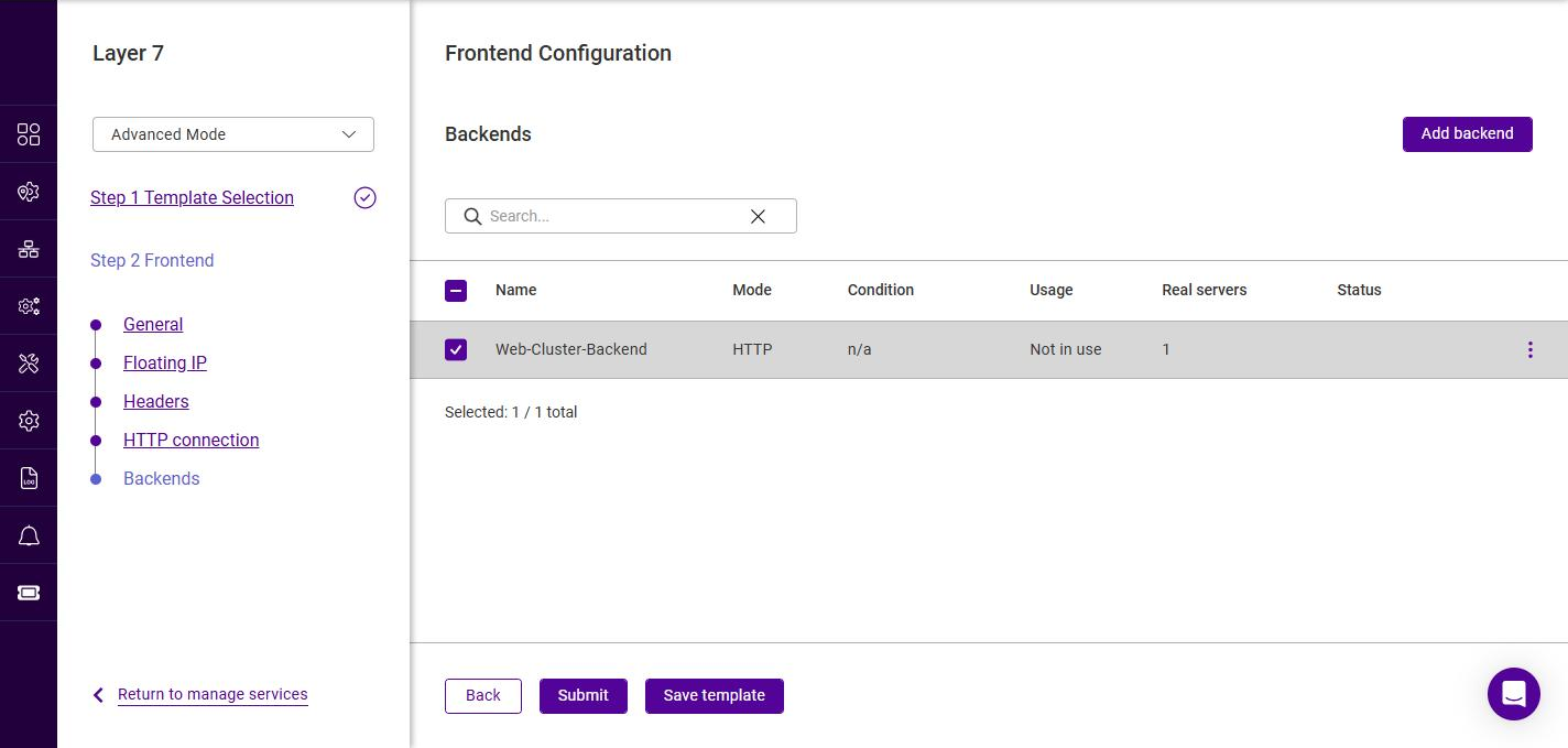
-
Ensure the required backend is selected, then click Submit to create the service.
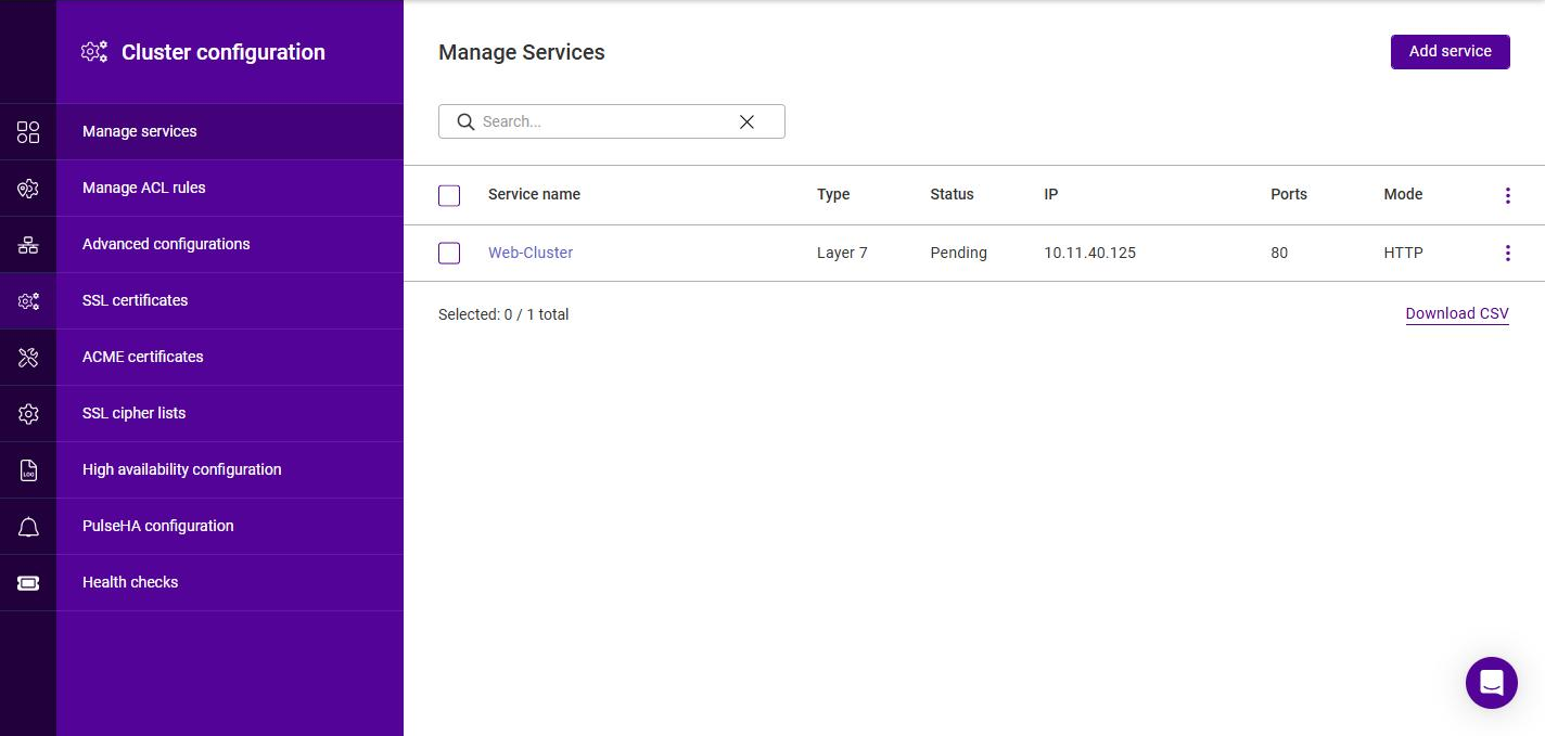
The service is created with a Status of Pending until the firewall and load balancing services are updated.
|
To activate the new service, the underlying services must be updated:
|
Duplicating Layer 7 Services
If you have existing Layer 7 Services, these can be duplicated. During the duplication process, the name and the IP address and/or port must be changed so that it does not clash with the source Service.
To duplicate an existing layer 7 Service:
-
Click the three dots menu next to the Service you’d like to duplicate.
-
Click Duplicate.
-
Update the Name for the new Service.
-
Update the Port if required.
-
Click Next.
-
Update the Floating IP address if required.
At least one of these settings must be changed. -
Click Update.
Modifying Layer 7 Services
Frontend
-
Navigate to Cluster Configuration > Manage services.
-
Click the three dots menu next to the service to be modified and select Edit.
-
Select the section to be modified in the area to the left. Make the changes required, click Next to step through the remaining sections, then click Submit to save the changes.
Transparency at Layer 7
HAProxy is a reverse proxy which means that a new connection is established from the proxy out to the backend server in response to an inbound client connection to the proxy. This means that the source IP address of the packet reaching the Real Servers will not be the client’s IP address, but an IP address owned by the load balancer. The source IP address applied depends on the configuration. By default, the IP address of the network interface is used, but this can also be configured to be any IP address that the load balancer owns using the Backend source address field of the Layer 7 service.
The load balancer can provide the actual client IP address to the Real Servers in two ways:
-
By inserting a header that contains the client IP source address. For HTTP traffic the X-Forwarded-For (XFF) header is used, for TCP traffic the Proxy Protocol Header is used.
For more information on XFF headers, please refer to Mozilla - X-Forwarded-For Header, for more information on Proxy Protocol headers, please refer to HAProxy Technologies - The PROXY Protocol. -
By modifying the Source Address field of the IP packets and replacing the IP address of the load balancer with the IP address of the client. The load balancer uses TProxy for this purpose.
In many cases, option 1 (using headers) can be used to achieve your objectives. Option 1 is easier to implement because there are no network topology requirements.
Inserting Headers
X-Forwarded-For (XFF) Headers
X-Forward-For headers are inserted by HAProxy when the layer 7 Service frontend option Enable X-forwarded-for header is enabled. A new X-Forwarded-For header is appended by the load balancer containing the client’s IP address. This information can then be extracted by the Real Servers for use in web applications or logging.
Proxy Protocol Headers
To configure HAProxy to send Proxy Protocol Headers, the layer 7 Service backend dropdown Send proxy protocol must be set to the required header version/type.
To configure HAProxy to receive Proxy Protocol Headers, the layer 7 Service frontend option Proxy protocol must be enabled. This will configure the layer Service to expect Proxy Protocol Headers for all connections. With this method, the layer 7 Service will only accept connections from sources that present Proxy Protocol Headers.
Using TProxy to modify the Source IP Address
Loadbalancer.org appliances utilize TProxy to modify the source IP address of each packet. TProxy is enabled per service using the Enable TProxy option on the Layer 7 service backend - edit the backend in Advanced Mode and enable Enable TProxy on the Backend Configuration - Layer 7 advanced step (for more information, see Backend Configuration - Layer 7 advanced). When TProxy is enabled, it’s important to be aware of the topology requirements for TProxy to operate correctly. Both one-arm and two-arm topologies are supported:
One-arm Deployments
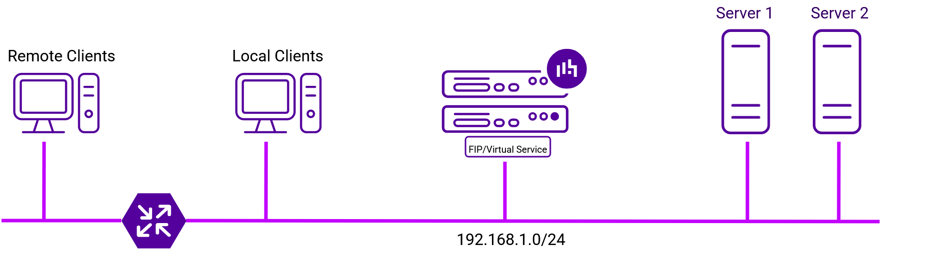
-
Here, the VIP is brought up in the same subnet as the Real Servers.
-
To support remote clients, the default gateway on the Real Servers must be an IP address on the load balancer and routing on the load balancer must be configured so that return traffic is routed back via the router.
| For a multi-node cluster, a floating IP should be added and used as the Real Server’s default gateway. This ensures that the IP address can "float" (move) between appliances. |
-
To support local clients, return traffic would normally be sent directly to the client bypassing the load balancer which would break TProxy. To address this, the routing table on the Real Servers must be modified to force return traffic to go via the load balancer.
Two-arm Deployments
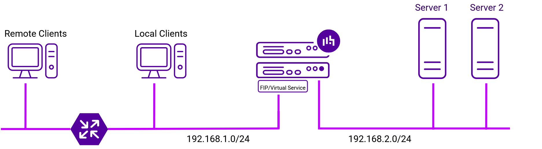
-
Here, two subnets are used. The VIP is located in one subnet and the load balanced Real Servers are located in the other. The load balancer requires two interfaces, one in each subnet.
| This can be achieved by using two network adapters, or by creating VLANs on a single adapter. |
-
The default gateway on the Real Servers must be an IP address on the load balancer.
| For a multi-node cluster, a floating IP should be added and used as the Real Server’s default gateway. This ensures that the IP address can "float" (move) between appliances. |
-
Clients can be located in the same subnet as the VIP or any remote subnet provided they can route to the VIP.
SSL/TLS Termination - Concepts
SSL/TLS termination can be handled in the following ways:
-
On the Real Servers (recommended) - aka SSL Passthrough
-
On the load balancer - aka SSL Offloading
-
On the load balancer with re-encryption to the Real Servers - aka SSL Bridging
| Terminating SSL on the load balancer can be very CPU intensive. In most cases, for a scalable solution, terminating SSL on the Real Servers is the best option. |
The following sections describe each method.
On the Real Servers (SSL Passthrough)
In this case, SSL certificates are installed on each Real Server in the normal way. Data is encrypted from the client all the way through to the Real Server, providing full end-to-end encryption.
The load balancer is configured with a Layer 7 service that listens on port 443 and distributes inbound requests to the Real Servers on port 443, as shown below:
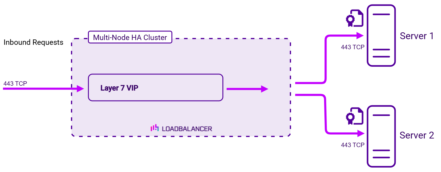
-
This is the recommended solution. It is the most scalable approach and avoids the CPU overhead of terminating SSL on the load balancer.
-
HTTP cookie persistence, header manipulation and other Layer 7 techniques that control how traffic is sent to the Real Servers cannot be used, because the data remains encrypted as it passes through the load balancer.
On the Load Balancer (SSL Offloading)
Here, the SSL certificate is installed on the load balancer. Data is encrypted from the client to the load balancer, then passed to the Real Servers unencrypted.
The load balancer is configured with a Layer 7 service that listens on port 443, handles decryption and load balancing, and forwards the decrypted requests to the Real Servers on port 80, as shown below.
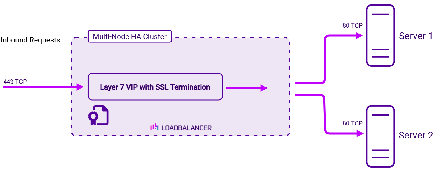
-
Certificates can be uploaded or created as explained in SSL Certificates.
-
Because the load balancer can see the unencrypted traffic, cookie based persistence, header manipulation and other Layer 7 techniques can be used to control traffic flow to the Real Servers.
On the Load Balancer with Re-encryption to the Real Servers (SSL Bridging)
Here, the SSL certificate is installed on both the load balancer and the Real Servers. Data is encrypted from the client to the load balancer, and re-encrypted from the load balancer to the Real Servers. This provides end-to-end encryption while still allowing the load balancer to inspect the traffic.
The load balancer is configured with a Layer 7 service that listens on port 443 and handles decryption, load balancing and re-encryption to the Real Servers on port 443, as shown below.
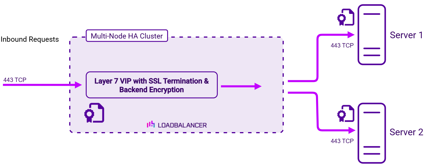
-
Certificates can be uploaded or created as explained in SSL Certificates.
-
Cookie based persistence, header manipulation and other Layer 7 techniques can be used to control traffic flow to the Real Servers.
Configuration
SSL Termination is configured within the Layer 7 Virtual Service. For more information, see Adding Layer 7 Virtual Services.
HTTP Headers - Configuration Examples
For HTTP Mode Virtual Services, HTTP header fields can be added, set, deleted, and replaced.
| For more information on configuring HTTP Headers, see Adding Layer 7 Virtual Services. |
The following examples illustrate how header rules can be used.
Example 1
A secure deployment requires that the X-Forwarded-For header field in client requests never be trusted. The header is under the control of the client and could potentially contain misinformation set by a malicious client. All header fields of this name should be deleted from incoming requests.
Create the following header rule:
| Type | Option | Name | Value |
|---|---|---|---|
Request |
Delete |
X-Forwarded-For |
- |
Example 2
A poorly designed web service behind the load balancer leaks sensitive information through an HTTP response header field. The vulnerable response field looks like so: Database-Engine: MongoDB_3.4.14. All header fields of this name should be deleted from outgoing responses.
Create the following header rule:
| Type | Option | Name | Value |
|---|---|---|---|
Request |
Delete |
Database-Engine |
- |
Example 3
A web service behind the load balancer expects to receive information about client requests via HTTP header fields. The service expects to receive the source IP address, destination IP address, and destination port of the client’s initial connection to the load balancer, which it expects to find in header fields named X-Client-Source, X-Client-Dest, and X-Client-Dest-Port, respectively. The load balancer should add these header fields to incoming requests and populate their values appropriately. The load balancer should also delete any pre-existing header fields that use the field names that the web service is logging, to prevent clients from tampering with or injecting arbitrary data into the web service’s logs.
Create the following header rules:
| Type | Option | Name | Value |
|---|---|---|---|
Request |
Set |
X-Client-Source |
%ci |
Request |
Set |
X-Client-Dest |
%fi |
Request |
Set |
X-Client-Dest-Port |
%fp |
GSLB Services
GSLB (Global Server Load Balancing) enables traffic to be load balanced across multiple geographically dispersed servers. When used in conjunction with the failover and high availability features of the appliance, GSLB enables highly available, multi-site load balanced environments to be created. GSLB functionality is provided using the Open Source Polaris GSLB.
Introduction
GSLB enables the load balancer(s) to provide intelligent DNS responses to inbound client queries for one or more sub domains. The responses given depend on the health of each endpoint and, if a topology (region) is configured, the location of those endpoints relative to the client making the request. Where GSLB is deployed alongside application load balancing, the endpoints are usually the VIPs that are configured at each site. Where application load balancing is not used and only GSLB is configured, the endpoints are normally the Real Servers.
DNS delegation is used to delegate responsibility for the sub domain(s) to the GSLB service on the load balancers. Once delegated, it is the GSLB service on the load balancers that is responsible for providing the response to DNS queries for that sub domain.
In a two site setup with an HA pair of load balancers in each site, once GSLB and DNS delegation are correctly configured, the four load balancers act as intelligent name servers for the sub domains specified.
Key features
-
Reliable health checking service supporting TCP, HTTP(S) and custom external checks so that only healthy members/endpoints are returned on lookups.
-
Failover, round robin and also a topology method that directs clients to servers in the same location.
-
Can return single or multiple (up to 1024) answers at once.
-
Option to fall back to any healthy server or refuse the query.
| For additional information, see our GSLB blog. |
In Endurance, a GSLB Service is configured using the same template-based wizard used for Layer 4 and Layer 7 Services. The wizard is split into 2 stages: Frontend Configuration (the sub domain that GSLB responds to) and Backend Configuration (the pool of endpoints that DNS queries are answered with, along with the health check and load balancing method).
The following table shows how the GSLB concepts map onto the wizard:
| Concept | Where it is configured |
|---|---|
Global name |
The Domain specified on the Frontend step. |
Pool |
The Backend - the General step defines the load balancing method and the Healthcheck step defines the health check. |
Members / endpoints |
The Real Servers added on the Backend > Real servers step. |
Topologies |
Regions. A Region is assigned to each Real Server, and Regions are defined under Network > Regions. For more details, see Regions. |
Adding a GSLB Service
The wizard can be run in 2 modes, selected using the drop-down at the top of the left-hand menu:
| Mode | Description |
|---|---|
Default Mode |
Displays only the most commonly used settings. Recommended for a quick, standard deployment. |
Advanced Mode |
Displays all available settings. |
| The steps below use Advanced Mode so that all available settings are described. When using Default Mode, the advanced settings are hidden and sensible defaults are applied automatically. |
To add a new GSLB Service:
-
Using the WebUI, navigate to Cluster Configuration > Manage Services and click Add service.
-
Select the GSLB template, then click Add GSLB Service.
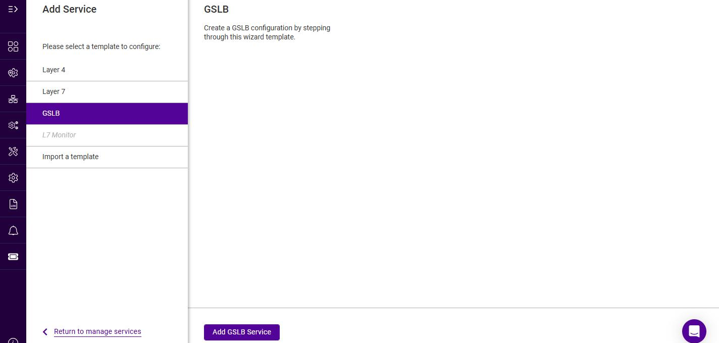
-
To display all settings, change the mode drop-down from Default Mode to Advanced Mode.
Frontend Configuration - General
-
Configure the frontend:
Setting Description Domain
The sub domain that GSLB responds to, for example www.example.com.
Time to live
How long (in seconds) to cache the DNS response. For example 3600 would be equal to 1 hour. The minimum value is 1 (1s); the default is 10.
-
Click Next.
Backend Configuration - General
-
Configure the backend:
Setting Description Name
A suitable name for the backend, e.g. example-pool.
Balance mode
The load balancing method to use. The options are described in the table below.
Refuse on failure
Determines the resolution behavior when all members of the pool are down (Advanced Mode only). When unchecked (default), the appliance distributes queries among all configured members that have a non-zero weight, ignoring their health status. When checked, all queries are refused.
Note: leaving this unchecked with all member weights set to 0 results in a NOERROR response with no answer section data.Max address returned
The maximum number of A records to return in a response (Advanced Mode only). Large responses are sent over TCP. Valid values are 1 to 1024; the default is 1.
The Balance mode options are:
Balance mode Description Weighted round robin
Round robin with weighting. The default option.
Topology weighted round robin
As above, but the topology (region) information is also considered, to direct clients to endpoints in the same region / data center.
Failover Group
The first healthy endpoint is handed out continuously unless it becomes unhealthy, in which case the next healthy endpoint is used, and so on. Can be used for active-backup scenarios. When this method is used, the order in which the Real Servers are listed should match the order in which they are intended to be used.
-
Click Next.
Backend Configuration - Healthcheck
This step configures the health check the load balancer uses to decide whether each endpoint is available. Only healthy endpoints are returned in DNS responses.
-
Select the required Healthcheck mode. The options are:
Healthcheck mode Description HTTP
Performs an HTTP GET request. The check succeeds if the expected response is returned.
HTTPS
As HTTP, but the request is made over SSL/TLS.
TCP
Attempts a TCP connection to the check port. Optionally, a string can be sent and the response matched against a regular expression.
No checks, always on
Disables health checking; all endpoints are permanently assumed to be up.
External Script
Runs a custom health check script on the appliance. The check receives the endpoint’s IP address and port, together with any additional parameters that are passed.
External Dynamic Weight
Runs a custom script that dynamically adjusts the weight of the endpoint based on its output. The script should output a value between 0 and 10, where 10 is the highest priority and 0 removes the endpoint from the pool.
-
Complete the fields for the selected mode. The available fields are:
Setting Description Healthcheck URL path
For HTTP / HTTPS. The URL path to request, appended after the endpoint’s IP address. The default is
/.Healthcheck hostname
For HTTP / HTTPS. The hostname to supply in the HTTP
Hostheader. When using HTTPS this is also supplied in SNI.Healthcheck send string
For TCP. A string to send after connecting to the port.
Healthcheck match RE
For TCP. A regular expression (not case sensitive) to match in the response.
Healthcheck script
For External Script / External Dynamic Weight. The health check script to run, selected from the drop-down. To add a script, see GSLB Health Check Scripts.
Healthcheck expected codes
For External Script / External Dynamic Weight. A string to match in the script’s output for the check to succeed.
Parameters
For External Script / External Dynamic Weight. A comma separated list of additional parameters to pass to the script.
Healthcheck port
The port to check.
Healthcheck interval
How often the check is performed, in seconds.
Healthcheck timeout (ms)
How long to wait for a response, in milliseconds.
Healthcheck retries
The number of times to retry a failed check before marking the endpoint down.
-
Click Next.
Backend Configuration - Real servers
The Real Servers are the endpoints that are returned to clients in DNS responses.
-
Click Add real server.
-
Configure the Real Server:
Setting Description Name
A suitable name for the Real Server, e.g. web-london.
IP
The IP address of the endpoint that is returned in DNS responses, e.g. 10.11.40.10.
Healthcheck IP
The IP address that is health checked. This is normally the same as the IP.
Weight
The weight of the endpoint. Valid values are 0 to 10; a weight of 0 disables the endpoint.
Regions
Assigns the Real Server to one or more Regions, used by the Topology weighted round robin balance mode to direct clients to endpoints in the same region. Select an existing Region, or click Add new region to create one. Regions are managed under Network > Regions - for more details, see Regions.
-
Click Add, then repeat to add additional Real Servers.
-
Ensure the required Real Servers are selected (checked).
Submitting the Service
-
Once all Real Servers have been added, click Submit to create the service.
The new GSLB Service is now listed under Manage Services with a Type of GSLB.
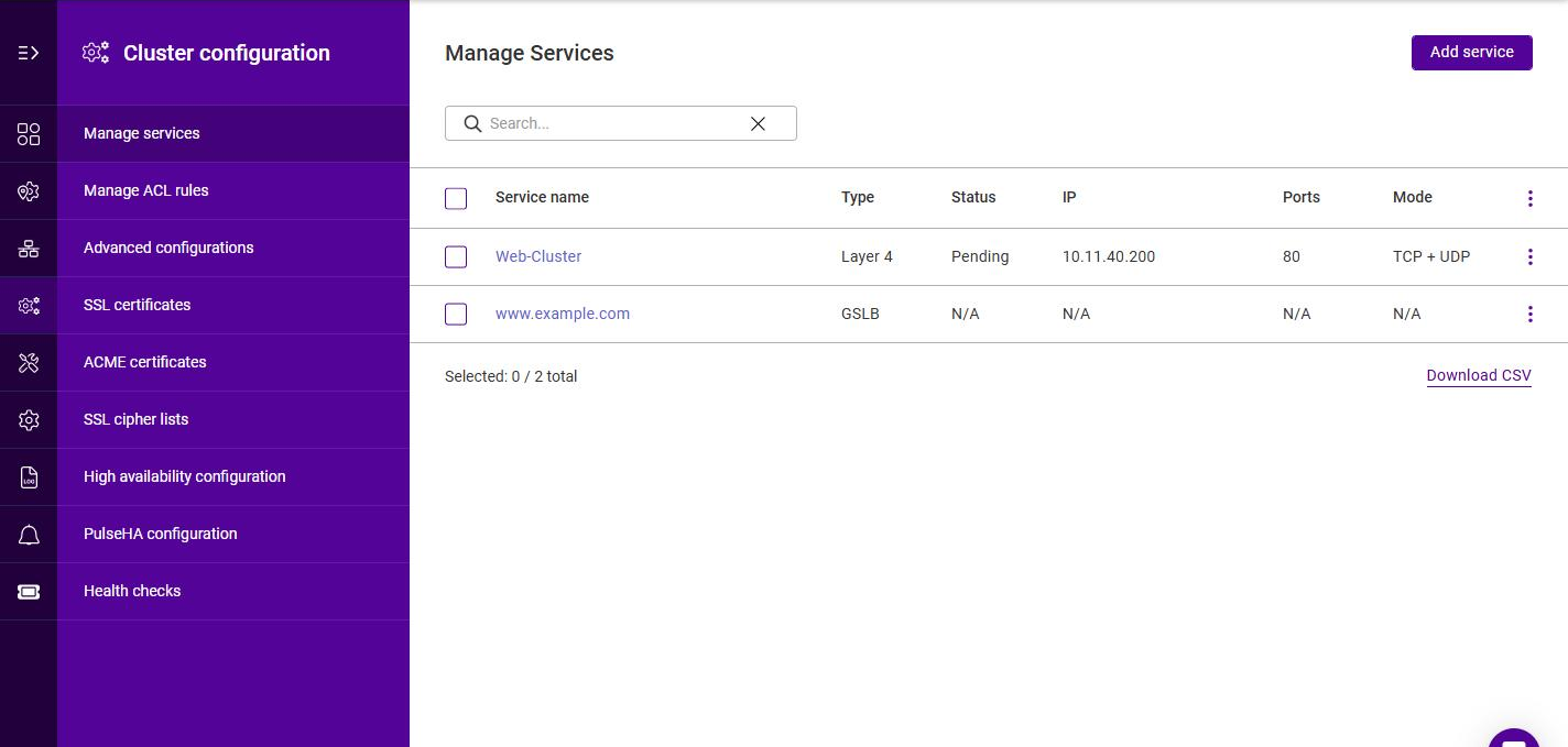
|
When the service is created, a notification indicates that the configuration of one or more services has changed. To apply the changes:
For more details, see System services. |
| By default, the GSLB service listens on TCP & UDP port 53 on all appliance IP addresses. |
GSLB Health Check Scripts
Custom GSLB health checks can be created using the WebUI, then selected on the Backend > Healthcheck step when the Healthcheck mode is set to External Script or External Dynamic Weight.
To add a GSLB health check script:
-
Using the WebUI, navigate to Cluster Configuration > Health checks and click Add health check.
-
Specify a suitable Name for the health check, e.g. GSLB-Custom-Check.
-
Optionally specify a Description.
-
Under Services, enable the GSLB checkbox.
-
Enter the script in the Script content editor.
-
Click Submit.
Once added, the health check appears in the Health Checks list and in the Healthcheck script drop-down on the Backend > Healthcheck step.
| The "Feedback_Agent_Weight" GSLB template can be used to create a dynamic weight health check script that interacts with the Loadbalancer.org Feedback Agent. For more details on health check scripts, see Health checks. |
Viewing the GSLB Configuration
The generated GSLB configuration can be viewed (read-only) using the WebUI menu option View Configuration > GSLB. Three tabs are available:
-
Database - the GSLB configuration database, showing the configured frontends, backends and Real Servers.
-
Polaris Lb - the Polaris load balancing configuration file.
-
Polaris topology - the Polaris topology (region) configuration file.