Appliance deployment
This chapter covers how the appliance is deployed - the hypervisors it is supported on and the resources a virtual appliance requires - then how its initial network settings are configured using the setup wizard, and how the WebUI is accessed for the first time.
Currently, Endurance is available to download in ISO format. The ISO image can be used to deploy a Virtual Appliance (VA) and also to install to hardware.
The latest ISO file can be downloaded from the Endurance download page if not done so already.
Virtual
Hypervisor Support
The ISO provides full support for the following Hypervisors:
| Hypervisor | Tools |
|---|---|
VMware |
open-vm-tools |
Hyper-V |
hyperv-daemons |
Proxmox |
qemu-guest-agent |
Xen-based platforms |
xe-guest-utilities-latest |
Nutanix |
nutanix-guest-tools |
All tools except Nutanix are auto installed based on the detected Hypervisor. The Nutanix tools must be installed manually.
| The ISO can be deployed to other hypervisors, but with limited hypervisor integration. |
Host Requirements
To run the Loadbalancer.org Endurance VA (irrespective of which Hypervisor is being used) the following basic server specifications must be met:
-
64bit CPU
-
Virtual Technology hardware support - either Intel-VT-x or AMD-V compliant CPUs
VA Resources
When the VA is created, we recommend the following virtual resources for a PoC or for low to medium throughput production applications:
-
2 vCPUs
-
4 GB RAM
-
50 GB drive
Resources required depend on multiple factors including the application being load balanced, the number of end users, the anticipated throughput, the underlying physical hardware running the hypervisor and whether you’ll be load balancing at Layer 4 or Layer 7. Therefore, it’s not realistic to make generic recommendations.
If you need assistance in determining the resources required for your deployment, please contact support.
Hardware
A range of hardware appliances will be announced soon. In the meantime, the ISO image can be deployed to any Rocky 10.x compatible hardware if required.
Configure Initial Network Settings
After power up, the following startup message is displayed on the appliance console:
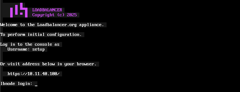
As mentioned in the text, initial network configuration can be performed at the console or via a browser. This will enable you to configure the management IP address and other network settings for the appliance.
| An IP address will be displayed if the appliance can obtain an address from a DHCP server. If not, no address will be shown and a static IP will first need to be assigned before the web based setup can be used. This can be done by logging in at the console as the "setup" user and selecting Set Static IP. |
| The wizard configures the appliance’s management interface only. Additional interfaces, subnets, Static, Floating and Service IPs, routing, firewall marks and all other network settings are configured from the WebUI once the appliance is up, as is any later change to the management interface itself. For details, see Network in the Administration Manual. |
At the Console
To start the console based setup process, login as the "setup" user. Once logged in, the Network Setup Wizard will start automatically.
Username: setup <Enter>
| A password is not required. |
A series of screens will be displayed that allow network settings to be configured:
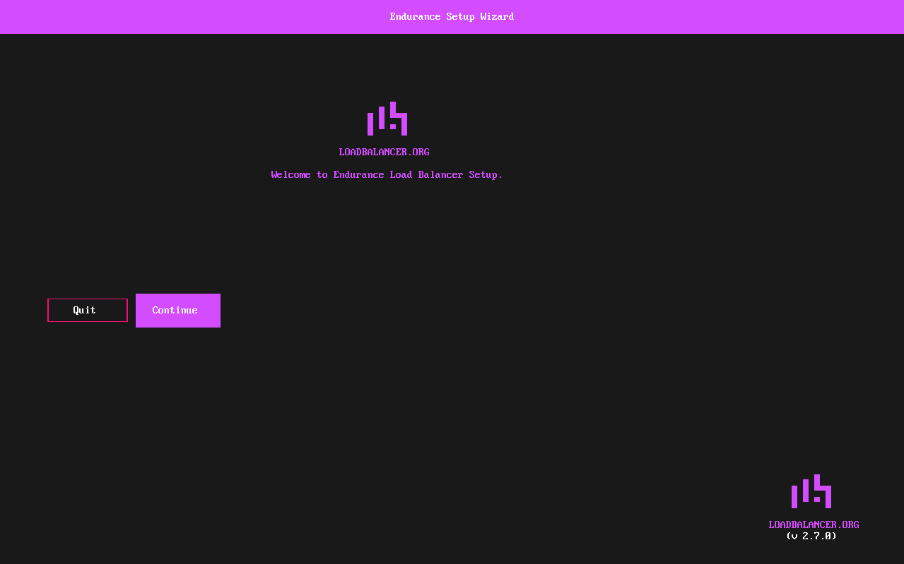
In the Welcome to Endurance screen, ensure Continue is selected and hit Enter to continue.
In the keymap screen, select the required keymap settings and hit Enter to continue. The list is long - press the first letter of a country to jump to it, and use the Up and Down arrow keys to move through the list. Once a country is selected, a second list of keyboard variants for that country is displayed; select the required variant and hit Enter.
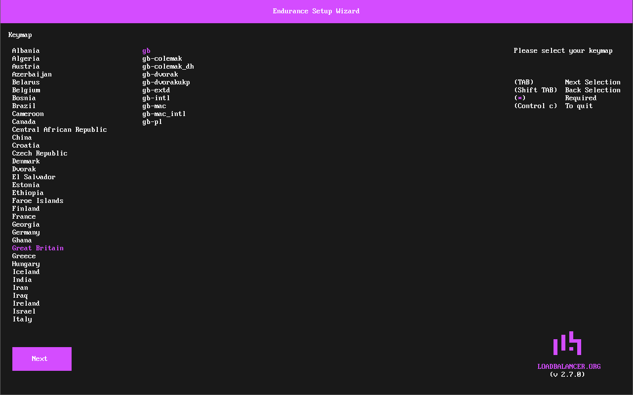
The Next button will be selected, hit Enter to continue.
In the Client Credentials screen, enter your Email, Password and Confirm Password. These will be used to login to the appliance’s WebUI. Hit Enter to continue.
| The password must be at least 8 characters long and contain at least 1 uppercase character, 1 lowercase character, 1 number and 1 special character. The permitted special characters are listed on screen. |
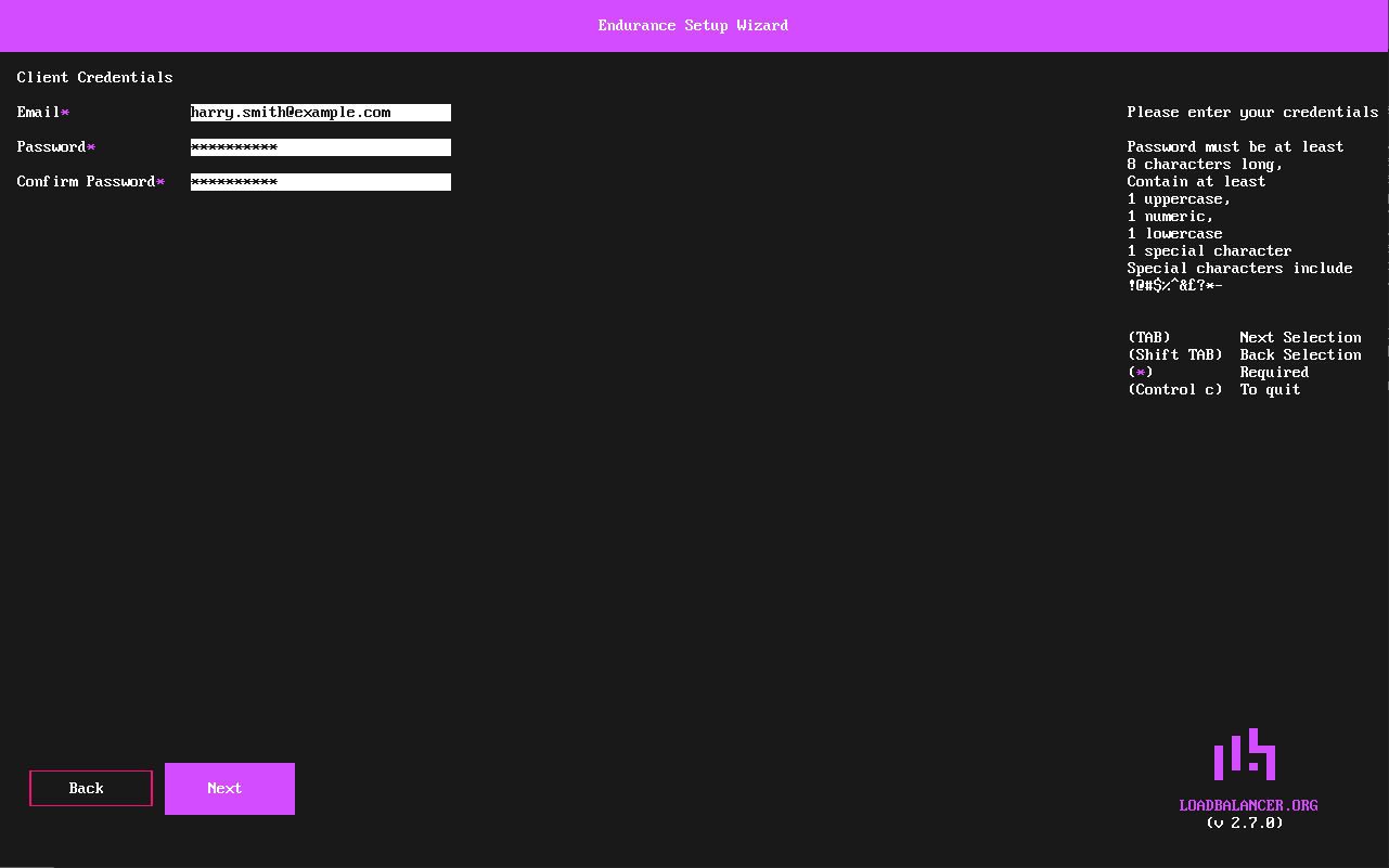
The Next button will be selected, hit Enter to continue.
In the Timezone screen, select the required region and hit Enter, then select the required city from the second list and hit Enter to continue. As with the keymap screen, press the first letter of an entry to jump to it and use the Up and Down arrow keys to move through the list.
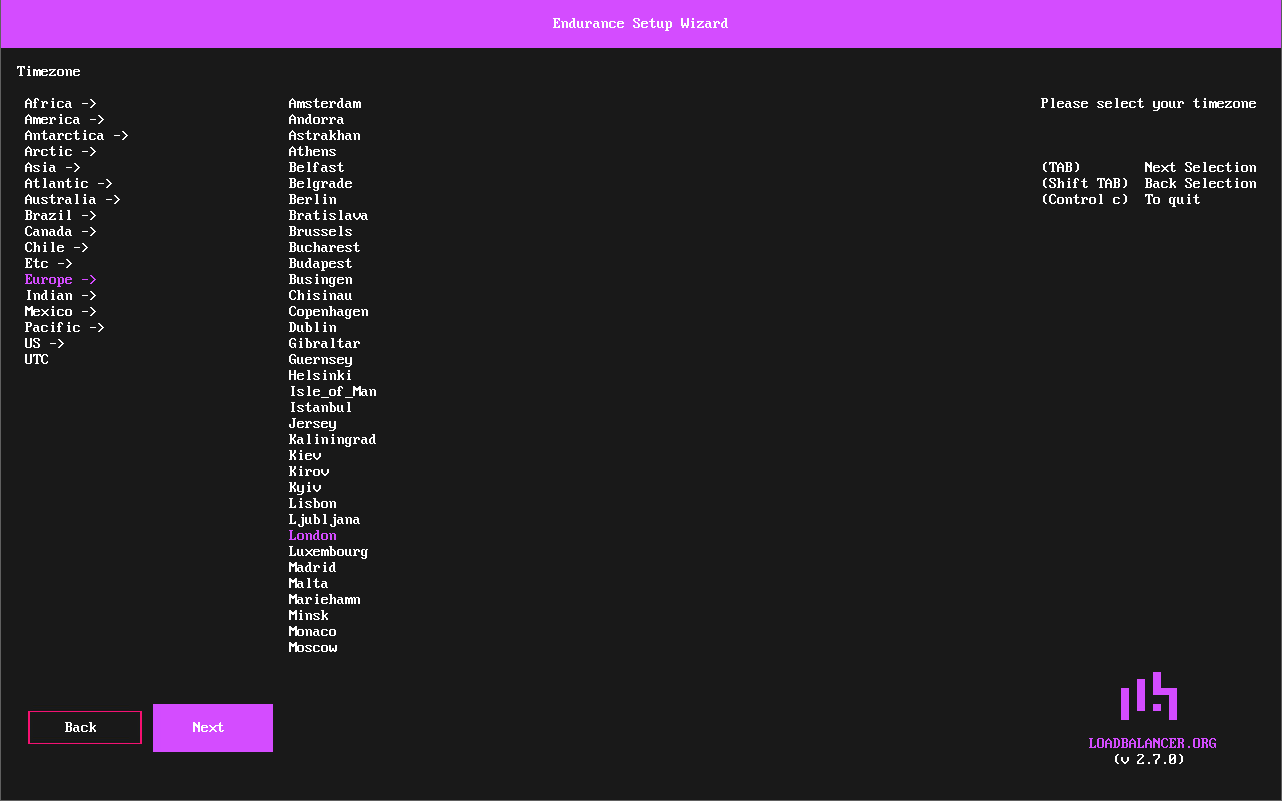
The Next button will be selected, hit Enter to continue.
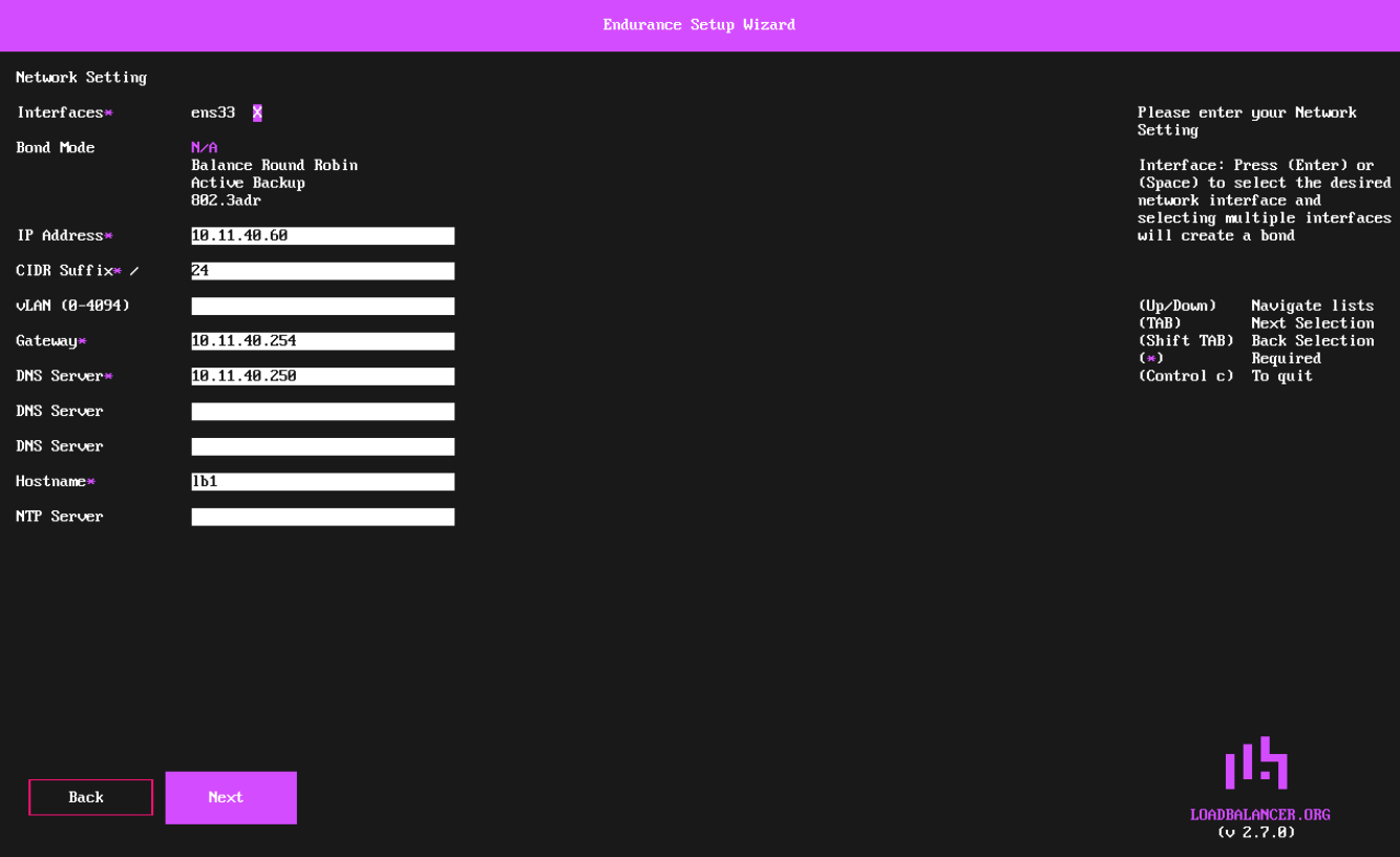
The Network Setting screen will be displayed.
-
Using the Spacebar, ensure that the Interface is selected.
-
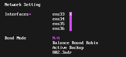
If additional adapters were added to the VA, additional interfaces will be displayed as shown below:
-
Select the required Interface(s). Where only one interface is selected, leave Bond Mode set to N/A. Multiple interfaces can be selected and bonded - in this case, select the required Bond Mode - the following options are available:
-
Balance Round Robin - This mode distributes network traffic across multiple network interfaces in a sequential, cyclic manner.
-
Active Backup - This mode places one of the adapters in a backup state and will only become active if the link is lost to the active adapter. This mode provides fault tolerance.
-
802.3ad - Dynamic link aggregation mode. This mode requires a switch that supports IEEE 802.3ad.
-
-
-
Set the required IP Address and CIDR Suffix.
A subnet mask such as 255.255.255.0 is not valid, in this case set the CIDR Suffix to 24. -
If required, set a vLAN ID in the range 0 - 4094.
-
Configure an appropriate Default Gateway and Hostname.
-
Configure at least one DNS Server. Three DNS Server fields are provided; only the first is required.
-
If an alternative time server is required, set the NTP Server. If this is left blank, pool.ntp.org is used.
-
Hit Enter to continue.
The Next button will be selected, hit Enter to continue.
In the Summary screen, check all settings. If you need to change anything, use the Back button. If everything is correct, ensure that Confirm selected and hit Enter to continue.
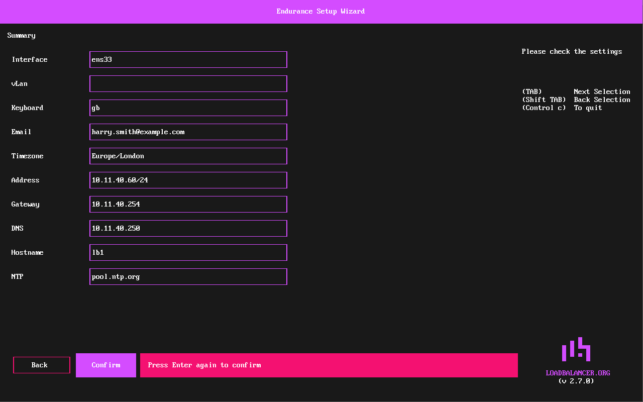
Hit Enter again to confirm. All settings will be applied.
A progress screen lists each configuration task as it is carried out:
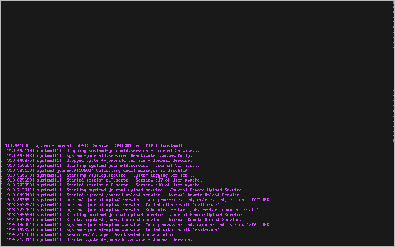
Once the configuration has been written, the Setup Complete screen will be displayed.
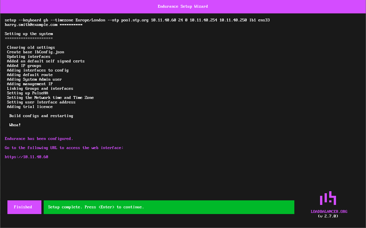
Hit Enter to exit the wizard and return to the command prompt.
Using a Browser
To start the web based setup process, browse to the IP address mentioned on the startup screen - if an IP address is not shown, login at the console as the "setup" user and select Set Static IP as mentioned previously.
The startup screen will be displayed:
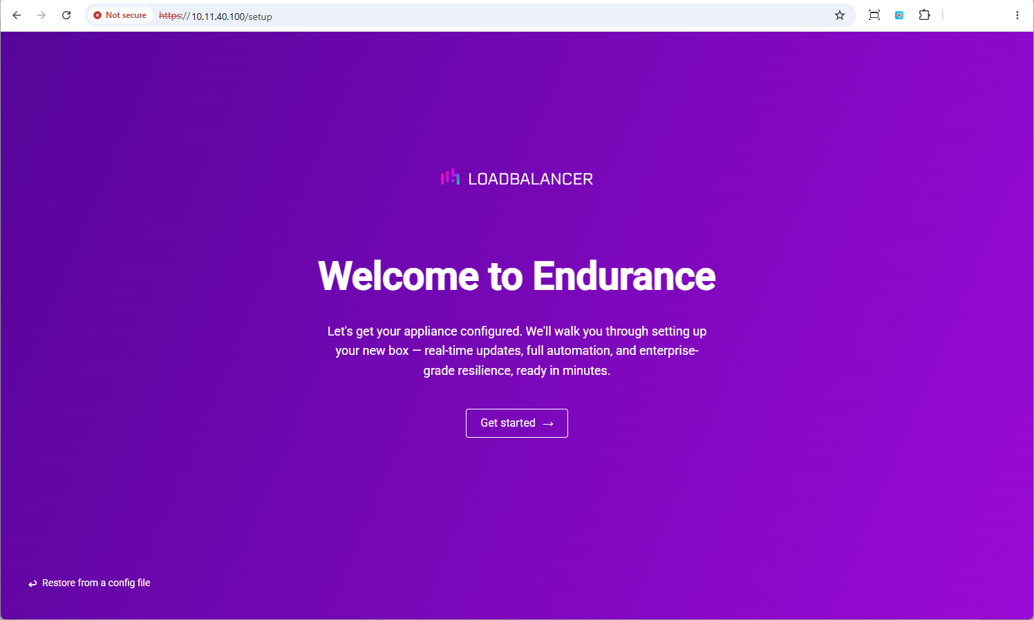
Click Get started to run the network setup wizard.
| Restore from a config file enables a previous configuration backup to be restored. |
In the keyboard screen, select the required Keymap. The drop-down lists keyboard layouts by language, e.g. English (UK), and includes a search box. Once a language is selected, a second drop-down is displayed for the specific variant, e.g. gb.
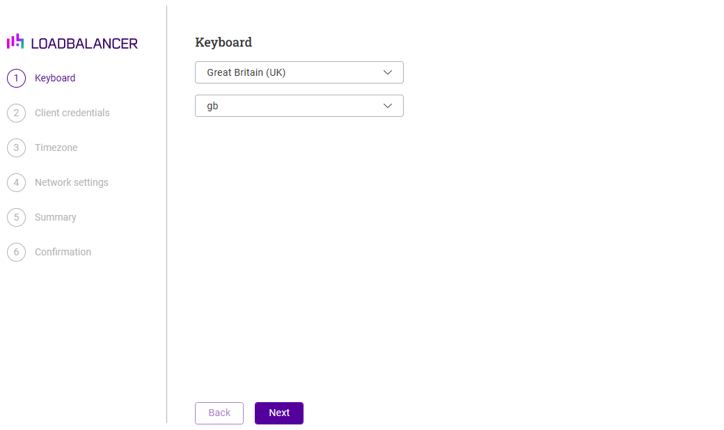
Click Next to continue.
In the Client Credentials screen, enter your Email and Password. These will be used to login to the appliance’s WebUI.
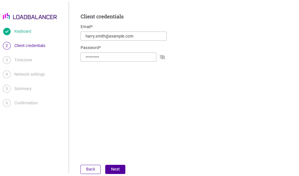
Click Next to continue.
In the Timezone screen, select the required region and city. The current appliance date and time are shown above the drop-downs, so the effect of the selection can be checked immediately.
The NTP servers used by the appliance are also set on this screen. pool.ntp.org is configured by default; change it if an alternative time server is required, and use Add to configure additional servers.
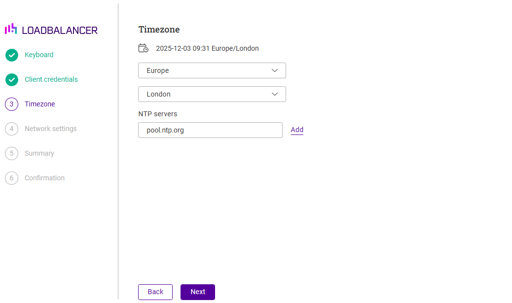
Click Next to continue.
In the Network Settings screen, configure the required network settings.
| This screen is used to configure the management interface. Additional interfaces must be configured using the WebUI. |
| Where the appliance obtained an address from a DHCP server, the IP, Mask, Gateway and Domain name servers fields are pre-populated with the values from the DHCP lease. Change them as required for the appliance’s permanent address. |
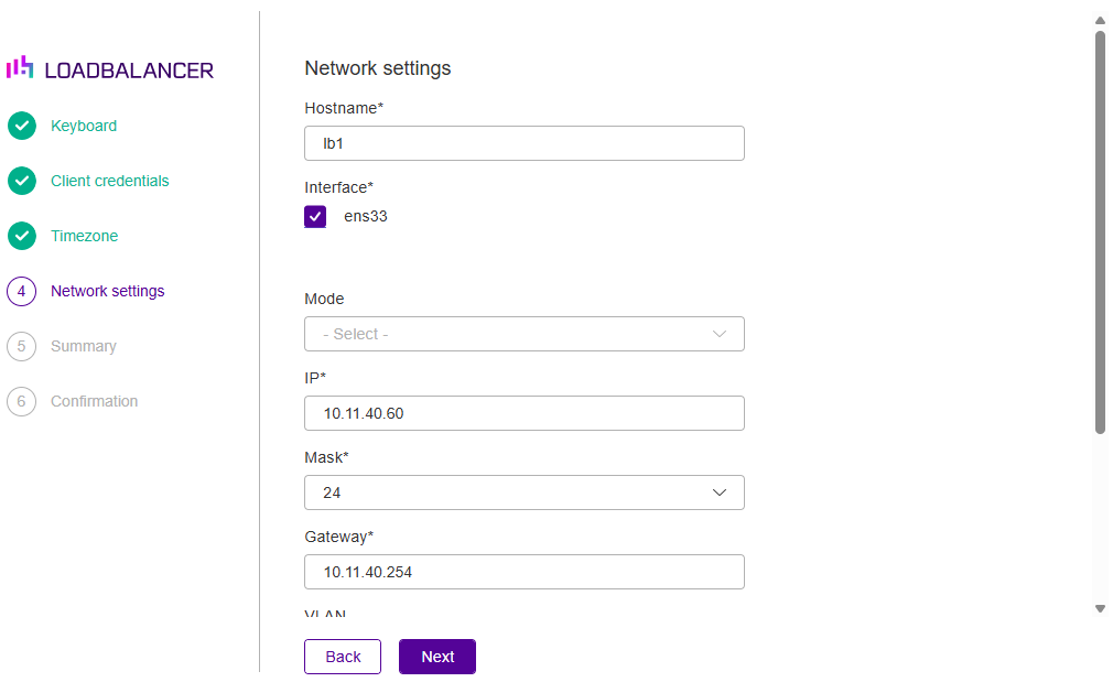
-
Specify an appropriate Hostname.
-
If additional adapters were added to the VA, additional interfaces will be displayed as shown below:
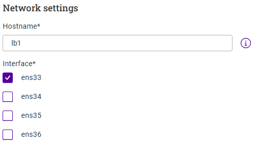
-
Select the required Interface(s). Multiple interfaces can be selected and bonded - in this case, select the required Bond Mode - the following options are available:
-
Balance Round Robin - This mode distributes network traffic across multiple network interfaces in a sequential, cyclic manner.
-
Active Backup - This mode places one of the adapters in a backup state and will only become active if the link is lost to the active adapter. This mode provides fault tolerance.
-
802.3ad - Dynamic link aggregation mode. This mode requires a switch that supports IEEE 802.3ad.
-
-
-
Set the required IP Address and select the required subnet Mask.
-
Configure an appropriate Default Gateway.
-
Scroll down to display the remaining fields.
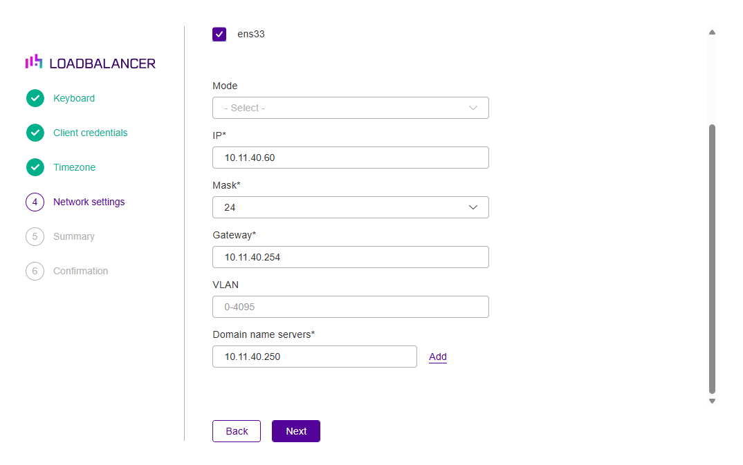
-
If required, set a VLAN ID.
-
Configure the required Domain name servers.
Click Next to continue.
In the License screen, choose how the appliance should be licensed. This can be changed at any time after setup - see Appliance Licensing.
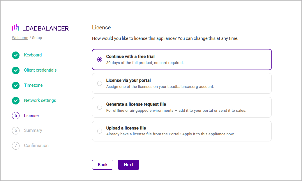
| Option | Description |
|---|---|
Continue with a free trial |
Runs the appliance on a 30 day trial of the full product. No card is required. This is the default option. |
License via your portal |
Assigns one of the licenses held on your Loadbalancer.org account. |
Generate a license request file |
Produces a request file for offline or air-gapped environments, which can be added to the Portal or sent to sales. |
Upload a license file |
Applies a license file that has already been obtained from the Portal. |
Click Next to continue.
In the Summary screen, check all settings. If you need to change anything, use the Back button.
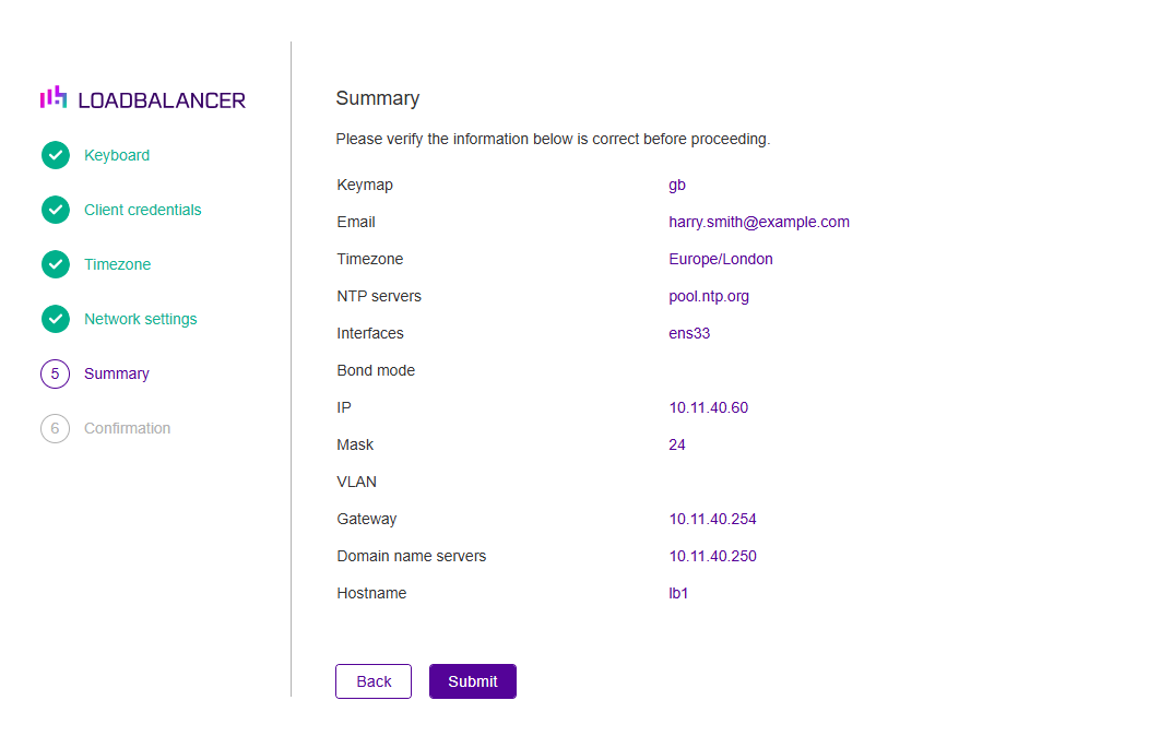
If everything is correct, click Submit.
Once the configuration has been written, the Confirmation screen will be displayed.
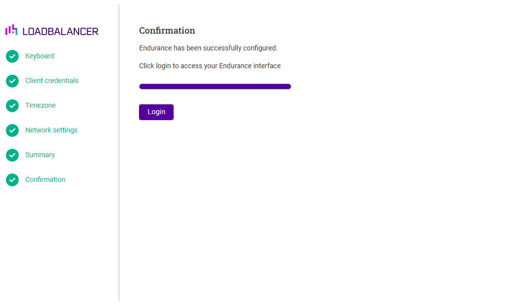
Click Login to open the WebUI login page for the appliance.
Accessing the Appliance WebUI
-
Using a browser, navigate to the following URL:
https://<IP-address-configured-during-the-network-setup-wizard>
You’ll receive a warning about the WebUI’s SSL certificate. This is due to the default self signed certificate that is used. If preferred, you can upload your own certificate. -
Log in to the WebUI using the following credentials:
Email: <configured-during-network-setup-wizard>
Password: <configured-during-network-setup-wizard>Once logged in, the WebUI will be displayed showing the main Dashboard.
WebUI Menu Options
The primary menu options are:
-
Dashboard - Real time monitor of all configured services and key system stats
-
Services - View and manage all configured services (Layer 4, Layer 7 or GSLB)
-
Manage services - Configure ACL rules, high availability, SSL/TLS and health checks
-
Network - Configure network settings such as interfaces, subnets, static, floating & service IPs, regions, routing and firewall marks. The View logs page is also located here
-
Settings - Manage all system, administration and maintenance settings and functions