Network Configuration
Configure the appliance’s network interfaces, IP addresses, bonding, VLANs, and routing.
Interfaces
The appliance ships with 4 interfaces, each interface can be used for any purpose. IP Groups (Subnets) are created and associated with an interface, Static IPs and Floating IPs can then be created within each subnet. Multiple interfaces can be bonded if required, VLANs can be configured for an interface or bond. This architecture allows subnets/IP addresses to be easily moved between interfaces.
To view all interfaces:
-
Using the WebUI, navigate to Network > Interfaces.
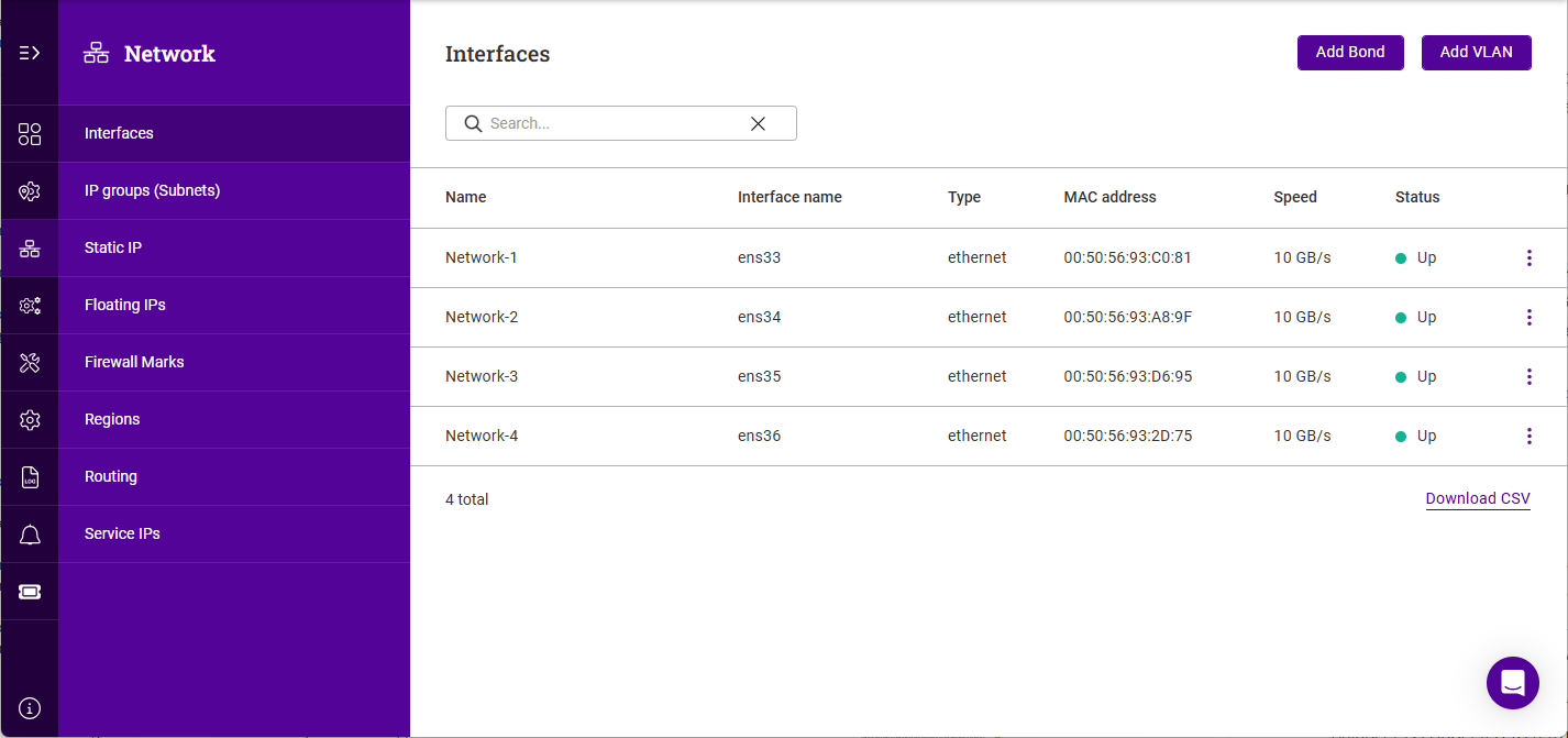
To view/edit an interface:
-
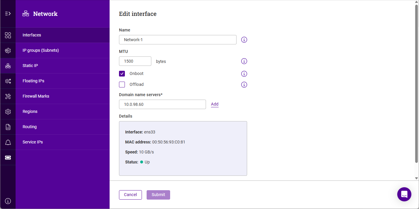
Click the three dots menu next to the Interface you’d like to view or edit.
-
Update the Name if required.
-
Update the MTU if required.
-
Enable (check) the Onboot checkbox to enable the interface on boot up.
-
Enable (check) the Offload checkbox to enable hardware NIC offloading (where available).
-
Configure the required Domain name servers for the interface.
-
Click Submit to save any changes.
Bonding
To Configure bonding:
-
Using the WebUI, navigate to Network > Interfaces.
-
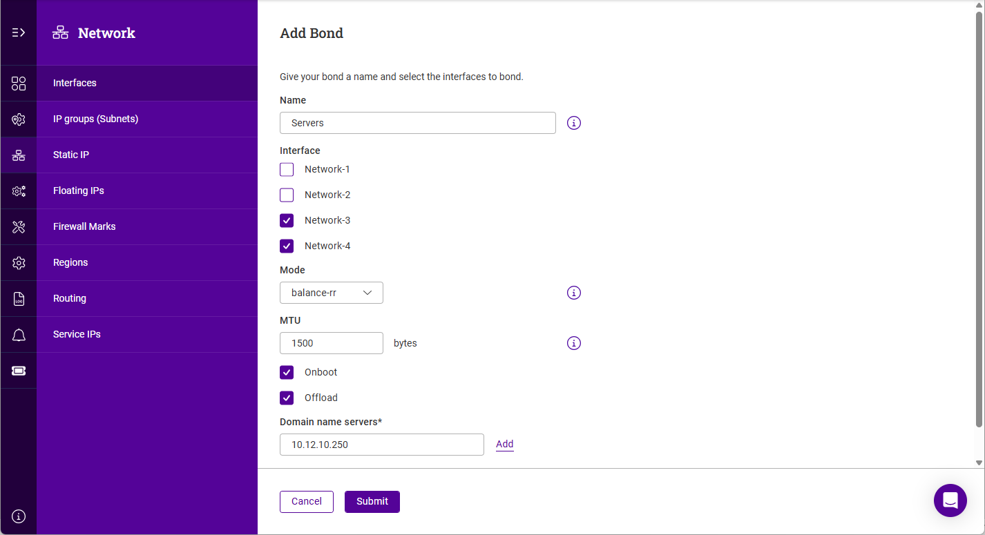
Click Add Bond.
-
Specify a Name for the bond.
-
Under Interface, select (check) the interfaces to be bonded.
-
Select the bonding Mode, the options are:
-
balance-rr - balance round robin. Transmits packets in a numerical order from the first available Secondary through to the last.
-
active-backup - This places one of the adapters in a backup state and will only become active if the link is lost to the active adapter. This mode provides fault tolerance.
-
802.3ad - Dynamic link aggregation mode. This mode requires a switch that supports IEEE 802.3ad.
-
-
Update the MTU if required.
-
Enable (check) the Onboot checkbox to enable the bond on boot up.
-
Enable (check) the Offload checkbox to enable hardware NIC offloading (where available).
-
Configure the required Domain name servers for the bond.
-
Click Submit.
| For multiple nodes in HA mode, configure bonding in the same way on each node. |
VLANs
802.1Q VLAN tagging allows the appliance to send and receive traffic for multiple VLANs over a single interface or bond.
In access mode switch ports are dedicated to one VLAN. The switch handles all the tagging and de-tagging of frames - the station connected to the port does not need to be configured for the VLAN at all.
In trunk mode the switch passes on the raw VLAN frames - the station connected must be configured to handle them. Trunk mode is usually used to connect two VLAN-carrying switches, or to connect a server or router to a switch.
If the load balancer is connected to an access mode switch port, no VLAN configuration is required. If the load balancer is connected to a trunk port, then all the required VLANs must be configured on the load balancer.
To add a VLAN:
-
Using the WebUI, navigate to Network > Interfaces.
-
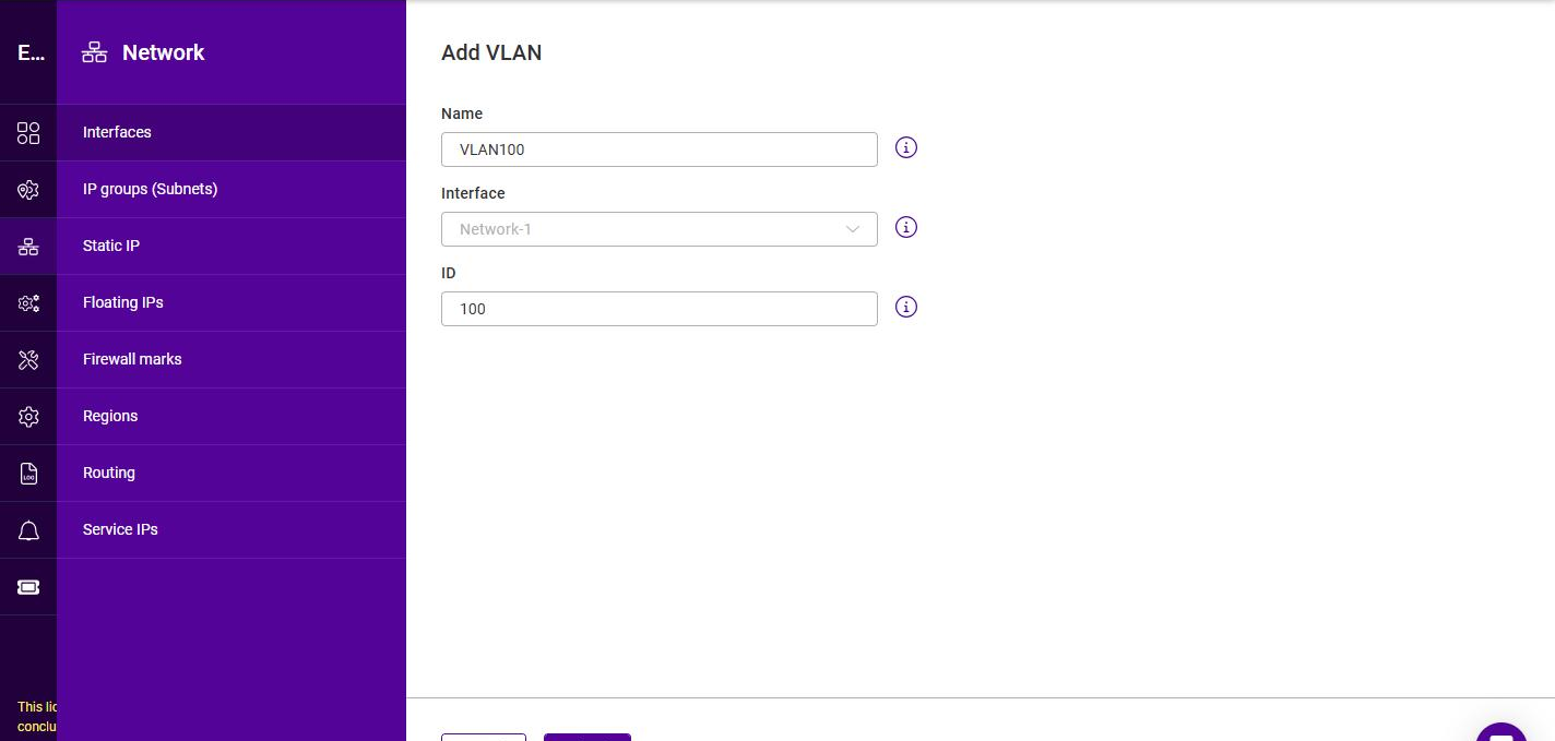
Click Add VLAN.
-
Specify a Name for the VLAN.
-
Select the Interface (or bond) to which the VLAN should be added.
-
Specify the VLAN ID (a value between 0 and 4095).
-
Click Submit.
| For multiple nodes in HA mode, configure VLANs in the same way on each node. |
IP Groups (Subnets)
-
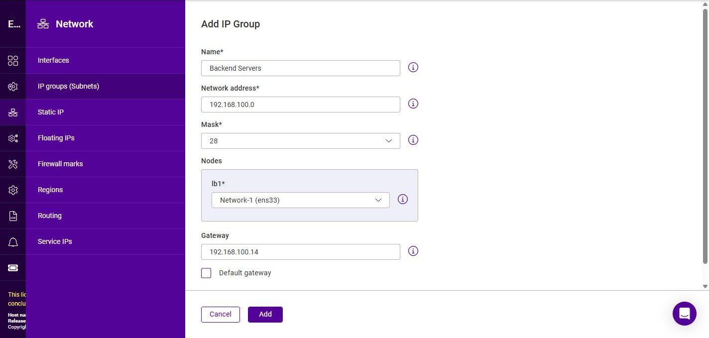
Using the WebUI, navigate to Network > IP groups (Subnets) and click Add IP group.
-
Specify a relevant Name, e.g. Backend Servers.
-
Specify the Network Address, e.g. 192.168.100.0.
-
Select the Mask from the drop-down, e.g. 28.
-
Under Nodes, select the Interface to use for this IP group on each node. For a single appliance only one node (e.g. lb1) is listed; for an HA pair, select the interface on each node.
-
Specify the Gateway, e.g. 192.168.100.14.
-
To use this gateway as the appliance’s default gateway, enable (check) the Default gateway checkbox.
-
Click Add.
| CIDR notation is used to specify the mask. For information on CIDR notation, see Appliance IPv4 Address Format (CIDR notation). |
Static IPs
Static IPs are used for:
-
The WebUI / API / SSH
-
Pulse (HA)
To add a Static IP:
-
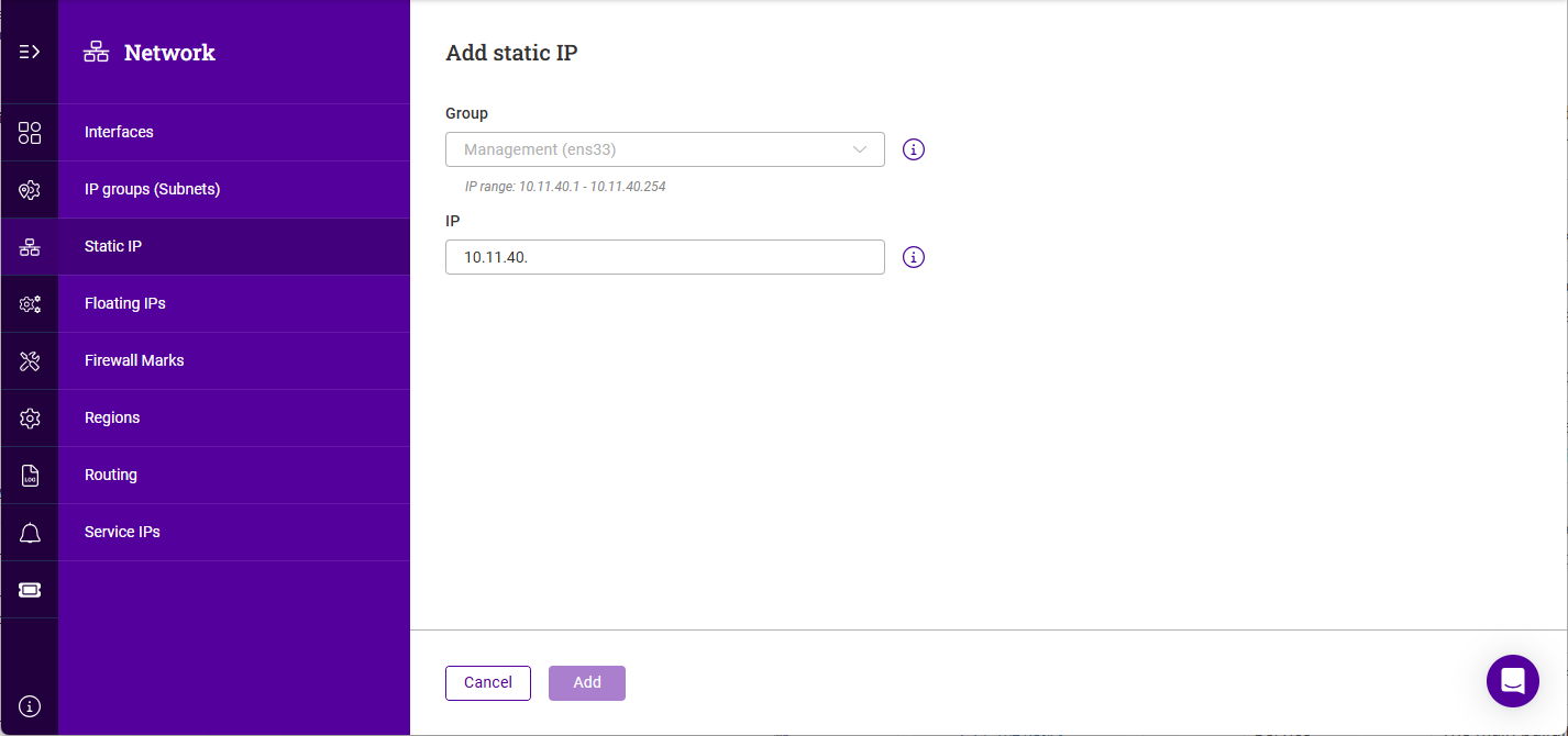
Using the WebUI, navigate to Network > Static IP and click Add static IP.
-
Select the relevant IP Group (subnet) from the Group drop-down. The valid IP range for the selected group is displayed below the field.
-
The network portion of the address will be auto-filled; complete the remainder of the address.
-
Click Add.
Floating IPs
Floating IPs are used for Virtual Services. This allows the Virtual Service to move or "float" between nodes.
They are also required when using layer 4 DNAT mode or Layer 7 proxy mode with TProxy where in both cases the load balancer must be the default gateway for the Real Servers. Again, this allows the Virtual gateway to move or "float" between nodes.
Floating IPs are controlled by Pulse to ensure that only the active node owns the Floating IP(s) at any time.
To add a floating IP:
-
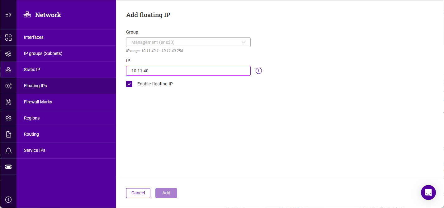
Using the WebUI, navigate to Network > Floating IPs and click Add Floating IP.
-
Select the relevant IP Group (subnet) from the Group drop-down. The valid IP range for the selected group is displayed below the field.
-
The network portion of the address will be auto-filled; complete the remainder of the address.
-
By default the address will be enabled once created. If this is not desired, disable (clear) the Enable floating IP checkbox.
-
Click Add.
Firewall Marks
Firewall marks are used to group ports and protocols into a single Virtual Service. For example, firewall marks can be used to bundle HTTP connections on port 80 and secure HTTPS connections on port 443 for an e-commerce site. By assigning the same firewall mark to each protocol, state information for the transaction can be preserved because the load balancer forwards all requests from a particular client to the same Real Server.
Firewall marks can also be used as a match condition when defining Policy Based Routing (PBR) routes.
To add a firewall mark:
-
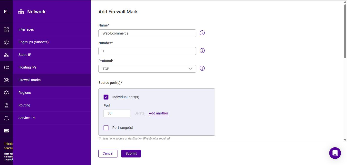
Using the WebUI, navigate to Network > Firewall marks and click Add firewall mark.
-
Specify a relevant Name.
-
Specify the Number - the firewall mark value to apply to matching packets.
-
Select the required Protocol, the options are None, TCP and UDP. Selecting TCP or UDP reveals additional Source port(s) and Destination port(s) sections; for each, specify the Individual port(s) and/or Port range(s) to match.
-
Configure the traffic to match. At least one Source IP/subnet or Destination IP/subnet must be specified. For each, select the Type and specify the Value:
Type Value Manual IP
A single IP address entered manually.
Manual Subnet
A subnet in CIDR notation entered manually.
Floating IP
An existing Floating IP, selected from a drop-down.
IP Group (Subnet)
An existing IP group, selected from a drop-down.
-
To match on more than one address, click Add another under the relevant section. To remove an entry, click Delete.
-
Click Submit.
Regions
A region is a named group of one or more subnets. Regions provide a convenient way to reference a collection of networks when configuring the appliance.
To add a region:
-
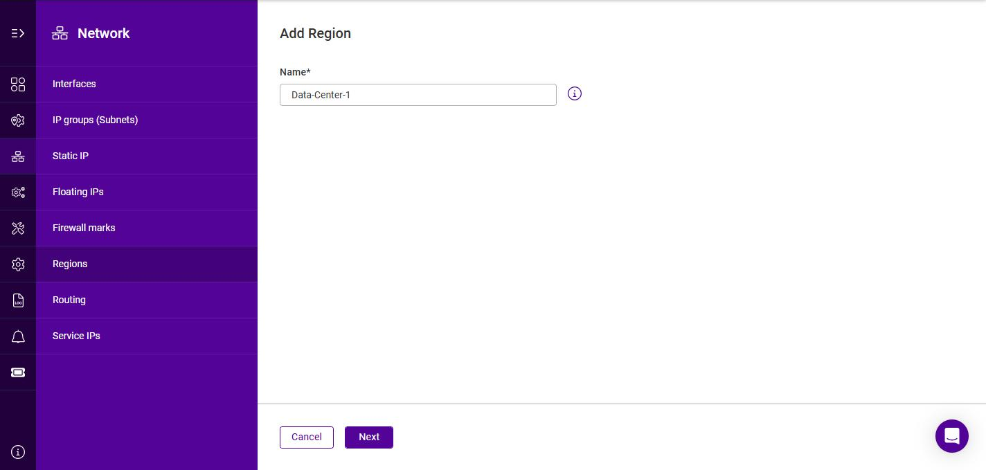
Using the WebUI, navigate to Network > Regions and click Add region.
-
Specify a Name for the region.
-
Click Next.
-
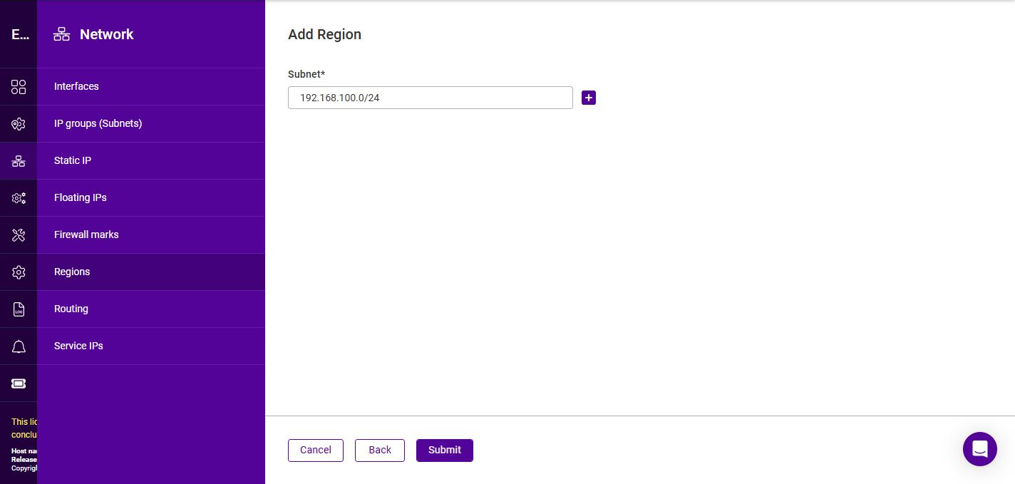
Specify a Subnet in CIDR notation, e.g. 192.168.100.0/24.
-
To add further subnets to the region, click the + button and specify each additional subnet.
-
Click Submit.
Once created, the Regions list shows each region together with the Count (the number of subnets it contains) and its Usage.
Routing
The appliance’s routing table is managed from a single Routing page. A default route (the appliance’s default gateway) is present by default. Additional routes can be added and are categorized by Type - Static, Local or PBR (Policy Based Routing).
To view the configured routes:
-
Using the WebUI, navigate to Network > Routing.
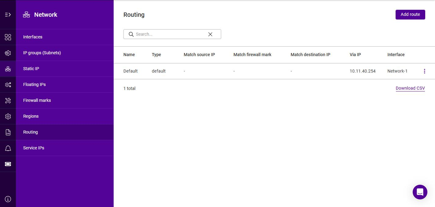
The list shows each route’s Name, Type, match conditions (Match source IP, Match firewall mark and Match destination IP), the gateway (Via IP) and the Interface.
To add a route:
-
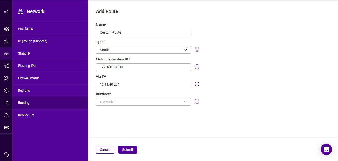
Click Add route.
-
Specify a Name for the route.
-
Select the required Type (Static, Local or PBR), then complete the fields for that type as described in the sections below.
-
Click Submit.
Static Routes
A static route directs traffic destined for a specific network via a defined gateway. Select the Static route type, then configure:
| Setting | Description |
|---|---|
Match destination IP |
The destination IP address to match for the static route. |
Via IP |
The address of the router (gateway) to forward matching packets to. |
Interface |
The interface to forward matching packets on. |
Local Routes
A local route adds a rule to the appliance’s local routing table for traffic matched by source IP address and/or firewall mark. Select the Local route type, then configure at least one of the following (Source IP or Firewall Mark is required):
| Setting | Description |
|---|---|
Match source IP |
The source IP address to match. |
Match firewall mark |
An existing firewall mark to match, selected from a drop-down. |
Policy Based Routing (PBR)
If you require a custom gateway for a particular Service, this can be achieved using PBR.
| If client source addresses are known and predictable, static routes should normally be used to route traffic. In other situations where this is not known or the network is large with many subnets, PBR can be used. Here, return traffic is routed based on the source address of the reply traffic (the VIP/floating IP) rather than on the destination address (the client’s IP). |
To configure a VIP to return traffic via a custom gateway rather than via the default gateway, select the PBR route type, then configure the following (at least one of Source IP or Firewall Mark is required):
| Setting | Description |
|---|---|
Match source IP |
The source IP address of the return traffic to match, e.g. the VIP / Floating IP. |
Match firewall mark |
An existing firewall mark to match, selected from a drop-down. |
Via IP |
The address of the router (gateway) to forward matching packets to. |
Interface |
The interface to forward matching packets on. |
Service IPs
A Service IP associates a name with an existing Static IP so that it can be used by appliance services. Service IPs are used for:
-
SNMP
-
Prometheus collector
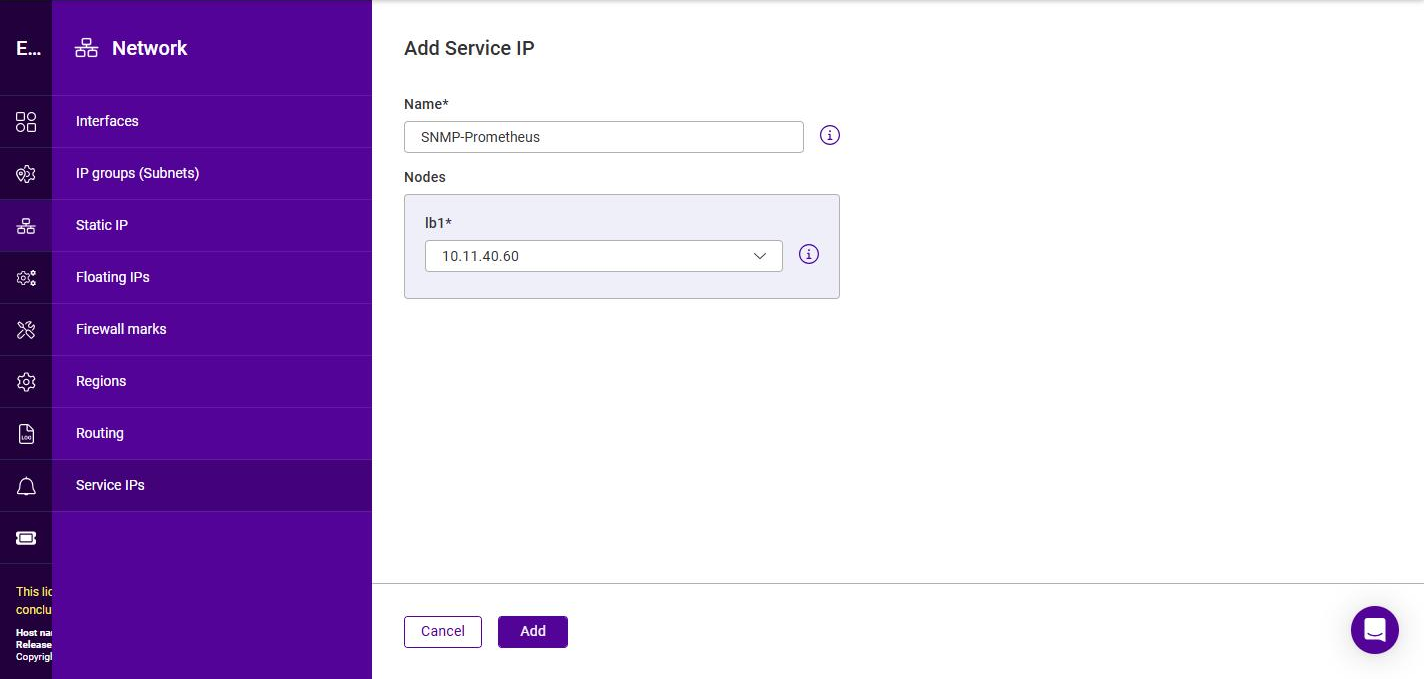
To add a Service IP:
-
Using the WebUI, navigate to Network > Service IPs and click Add service IP.
-
Specify a Name for the Service IP.
-
Under Nodes, select the Static IP to use on each node. For a single appliance only one node (e.g. lb1) is listed; for an HA pair, select the Static IP on each node.
-
Click Add.